Electromagnetic vibrator and producing method

a technology of vibrator and electric field, applied in the direction of electrical transducer, dynamo-electric machine, transducer details, etc., can solve the problems of unstable bonding of speaker parts via glue, inability to ensure the quality and stability of products, and inability to produce speakers with simple manufacturing methods, so as to reduce the manufacturing cost of speakers and facilitate production. , the effect of simplifying the method of making speakers

Active Publication Date: 2010-09-02
NINGBO SHENGYA ELECTRONICS
View PDF13 Cites 17 Cited by
  • Summary
  • Abstract
  • Description
  • Claims
  • Application Information

AI Technical Summary

Benefits of technology

[0007]Another object of the present invention is to provide an electromagnetic vibrator, wherein the special bonding structure of the upper basin frame can replace the traditional complicated glue process, so that the method for making the speaker is simplified, so as to minimize the manufacturing cost thereof.
[0008]Another object of the present invention is to provide an electromagnetic vibrator, wherein the production rate is enhanced by using machinery equipments

Problems solved by technology

It is seldom that the bonding via the glue is formed via chemical bonding force, which has stronger bonding force than Van der War force or Hydrogen bonding force, so that the bonding of the parts of speaker via the glue is unstable.
Therefore, the manufacturing method for producing the speaker is complicated and unable to ensure the quality and stability of the products, so as to limit its applications.
For example, the vibration sheet is adhesively mounted at the suspension edge via glue, wherein when a viscosity of the glue is too high, the glue can not be squeezed out of the gluing machine; when the viscosity of the glue is too low, the glue may overflow to decrease the perfor

Method used


Image

  • Electromagnetic vibrator and producing method
  • Electromagnetic vibrator and producing method
  • Electromagnetic vibrator and producing method

Examples


Embodiment Construction

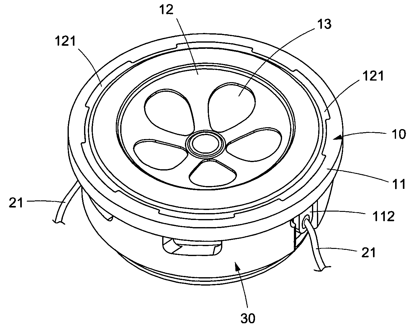
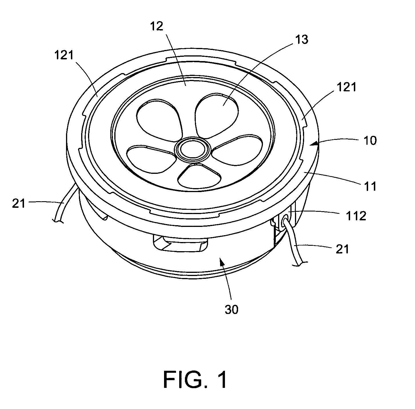
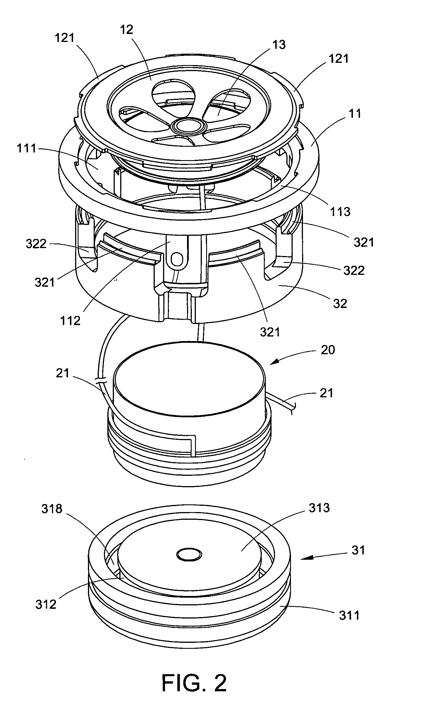
[0033]Referring to FIGS. 1 to 3 of the drawings, an electromagnetic vibrator specifically for a speaker according to a preferred embodiment of the present invention is illustrated, wherein the electromagnetic vibrator comprises an upper basin frame 10, an induction coil 20, and a lower basin frame 30.

[0034]As shown in FIGS. 2 to 6, the upper basin frame 10 comprises a supporting frame 11, a suspension edge element 12, and a vibration sheet 13 supported within the suspension edge element 12, wherein the supporting frame 11, having a ring shaped, has a through opening 111, two conductive terminals 112, a plurality of slots 113 and a plurality of first protruding elements 114. The through opening 111 is located at a center portion of the supporting frame 11. The conductive terminals 112 are affixedly provided at a bottom side of the supporting frame 11 in an integrated structure. The slots 113 are spacedly located at the supporting frame 11 at a position that the slots 113 are spacedly...


PUM


Abstract

An electromagnetic vibrator includes an upper basin frame, an induction coil, and a lower basin frame, wherein the upper basin frame includes a supporting frame, a vibration sheet, and a suspension edge element. The vibration sheet and the suspension edge are integrally formed together via mold injecting, so as to achieve variety of style and colors of the speaker. The manufacturing method of the electromagnetic vibrator improves the traditional producing process of a speaker by minimizing the gluing procedure thereof. The machinery equipments replace the traditional manual process. The special coupling structure and unique process of the electromagnetic vibrator also reduce the amount of using glue, so that the manufacturing cost is minimized, the un-stability of manually operation process is minimized, the quality and production rate is enhanced, and the process is relatively more environmental friendly.

Description

BACKGROUND OF THE PRESENT INVENTION[0001]1. Field of Invention[0002]The present invention relates to an acoustic vibration apparatus, and more particularly to a speaker using electromagnetic force to generate a mechanical vibration for generating a sound and a method thereof.[0003]2. Description of Related Arts[0004]As known by most of the people, the speaker is an electronic sound device for converting an electrical energy to sound energy. There are variety types of speakers. Though the principles of each of the speakers may be different, the speakers generally produce a mechanical vibration to vibrate the surrounding air, so that the air medium is being vibrated to form an electric-force-sound conversion system. Most of the current speakers are electric type loudspeaker. The conventional manufacturing process for making traditional speaker comprises the steps of glue the T iron or U iron, glue a basin frame with a magnetic element, and integrating upper plate, vibration sheet, coi...

Claims


Application Information

Patent Timeline
IPC IPC(8): H04R1/00
CPCH04R31/006H02K33/16H04R9/06
Inventor HUANG, HSIN MIN
Owner NINGBO SHENGYA ELECTRONICS
Why Eureka
Try Eureka