Sensor, a sensor array, and a method of operating a sensor

a sensor array and sensor technology, applied in the field of sensors, can solve the problems of affecting the accuracy of the signal to noise ratio of the conventional sensor chip, and achieve the effects of improving the accuracy of the calibration parameters, suppressing the time drift effect, and improving the signal accuracy

Inactive Publication Date: 2010-09-02
NXP BV
View PDF19 Cites 22 Cited by
  • Summary
  • Abstract
  • Description
  • Claims
  • Application Information

AI Technical Summary

Benefits of technology

[0055]According to an exemplary embodiment, a calibration row may be provided having one or more calibration units each of which being constituted as each of the plurality of sensors but being free of an electrode and a sensor active region. In other words, such a calibration row may have sensors which are only void of the electrode and the sensor active regions. However, all the other components of a sensor may be present in such a calibration unit, so that the measurement of a signal at such a calibration unit may be a proper measure for an unspecific underground signal which is detected by the other sensors as well. Since only the interaction with the particles to be detected lacks for the calibration unit, the use of a calibration row may allow to improve the accuracy of the signals by allowing to calibrate the measured signals on the basis of the underground signal determined by the calibration unit. Alternatively two or more calibration rows may be operated simultaneously to create a larger calibration signal (this may be advantageous to compensate for the effect of the lacking electrodes in the calibration rows). Additionally or alternatively to a calibration row, it is also possible to provide a single calibration cell or a calibration column.
[0056]By using an entire row comprising a plurality of calibration units, an average over the i

Problems solved by technology

Conventional sensor chips may suffer from a

Method used


Image

  • Sensor, a sensor array, and a method of operating a sensor
  • Sensor, a sensor array, and a method of operating a sensor
  • Sensor, a sensor array, and a method of operating a sensor

Examples


Embodiment Construction

[0081]The illustration in the drawing is schematic. In different drawings, similar or identical elements are provided with the same reference signs.

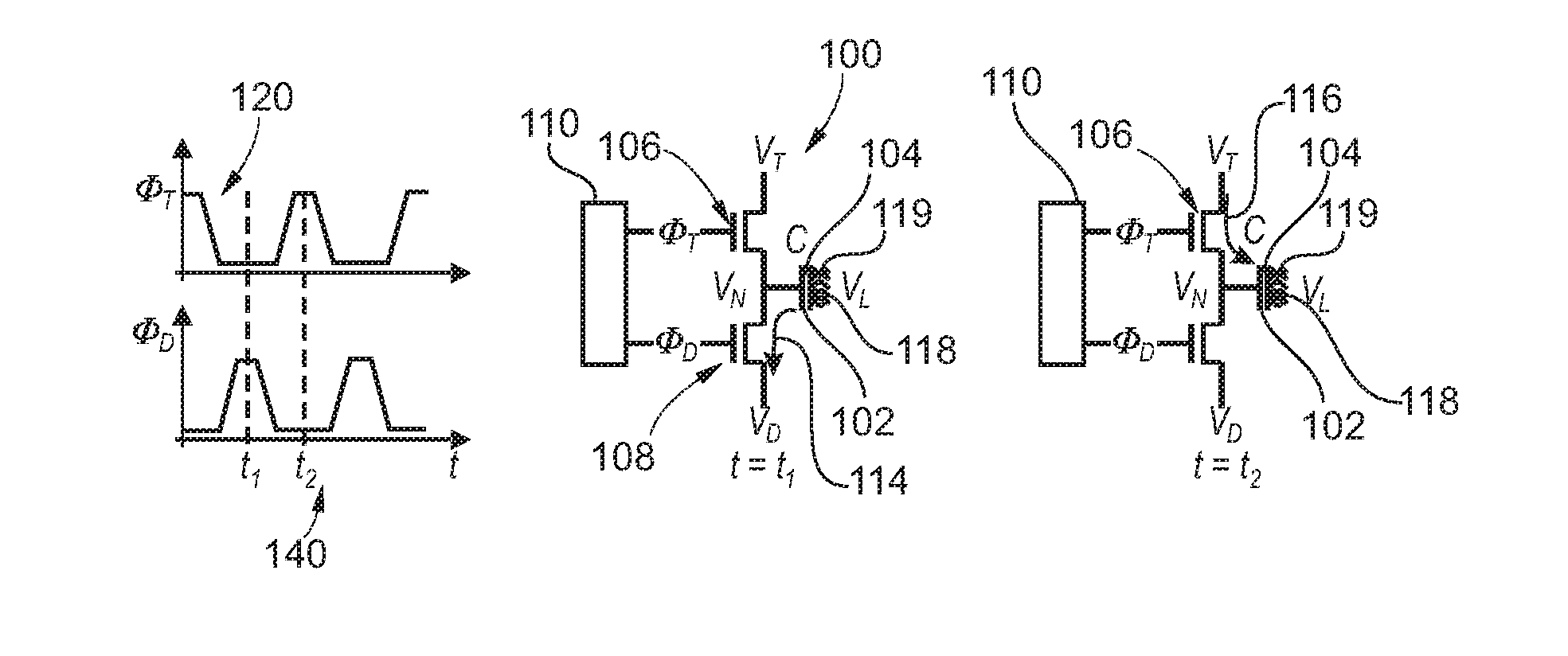
[0082]In the following, referring to FIG. 1, a biosensor 100 according to an exemplary embodiment of the invention will be explained.

[0083]The biosensor 100 is adapted for detecting biological particles (not shown in FIG. 1). The biosensor 100 comprises an electrode 102 as a first capacitor plate of a capacitor denoted with C in FIG. 1. A second capacitor plate is formed by an electrolyte electrode 118 (for instance in a manner similar to FIG. 2). An electrolyte 119 is connected by a separate further electrode (not shown) to connect it to an electrical potential VL.

[0084]A sensor active region 104 covers the electrode 102 and is sensitive for the biological particles.

[0085]A first field effect switch transistor 106 is provided which is operable to bring the electrode 102 to a first electric potential VT when the first switch element 106 ...


PUM

PropertyMeasurementUnit
Electrical resistanceaaaaaaaaaa
Ratioaaaaaaaaaa
Electric potential / voltageaaaaaaaaaa

Abstract

In an example embodiment, there is a sensor for detecting particles. The sensor comprises an electrode, a sensor active region covering the electrode and the sensor active region is sensitive-for the particles. A first switch element is operable to bring the electrode to a first electric potential when the first switch element is closed, and a second switch element is operable to bring the electrode to a second electric potential when the second switch element is closed. A detector is adapted to detect the particles based on a change of the electric properties of the sensor in an operation mode in which the electrode is brought to the first electric potential and an operation mode in which the electrode is brought to the second electric potential.

Description

FIELD OF THE INVENTION[0001]The invention relates to a sensor.[0002]Furthermore, the invention relates to a sensor array.[0003]Moreover, the invention relates to a method of operating a sensor.BACKGROUND OF THE INVENTION[0004]A biosensor may be denoted as a device which may be used for the detection of an analyte that combines a biological component with a physicochemical or physical detector component.[0005]For instance, a biosensor may be based on the phenomenon that capture molecules immobilized on a surface of a biosensor may selectively hybridize with target molecules in a fluidic sample, for instance when an antibody-binding fragment of an antibody or the sequence of a DNA single strand as a capture molecule fits to a corresponding sequence or structure of a target molecule. When such hybridization or sensor events occur at the sensor surface, this may change the electrical properties of the surface which can be detected as the sensor event.[0006]US 2004 / 0110277 discloses a bi...

Claims


Application Information

Patent Timeline
IPC IPC(8): G01N33/563G01N33/50G01N27/00
CPCG01N33/5438Y10T436/143333C12Q1/6825
Inventor WIDDERSHOVEN, FRANCISCUS
Owner NXP BV
Why Eureka
Try Eureka