AI technical title is built by Patsnap AI team. It summarizes the technical point description of the patent document.
a technology of blow molding machine and associated mechanism, which is applied in the field of machine and a method for blow molding containers, can solve the problems of mold closing, mold movement head, mold flaws in containers, etc., and achieve the effect of improving the quality of molded containers and reducing the number of molds
Inactive Publication Date: 2010-09-09
GRAHAM PACKAGING CO LP
View PDF13 Cites 23 Cited by
Summary
Abstract
Description
Claims
Application Information
AI Technical Summary
This helps you quickly interpret patents by identifying the three key elements:
Problems solved by technology
Method used
Benefits of technology
Benefits of technology
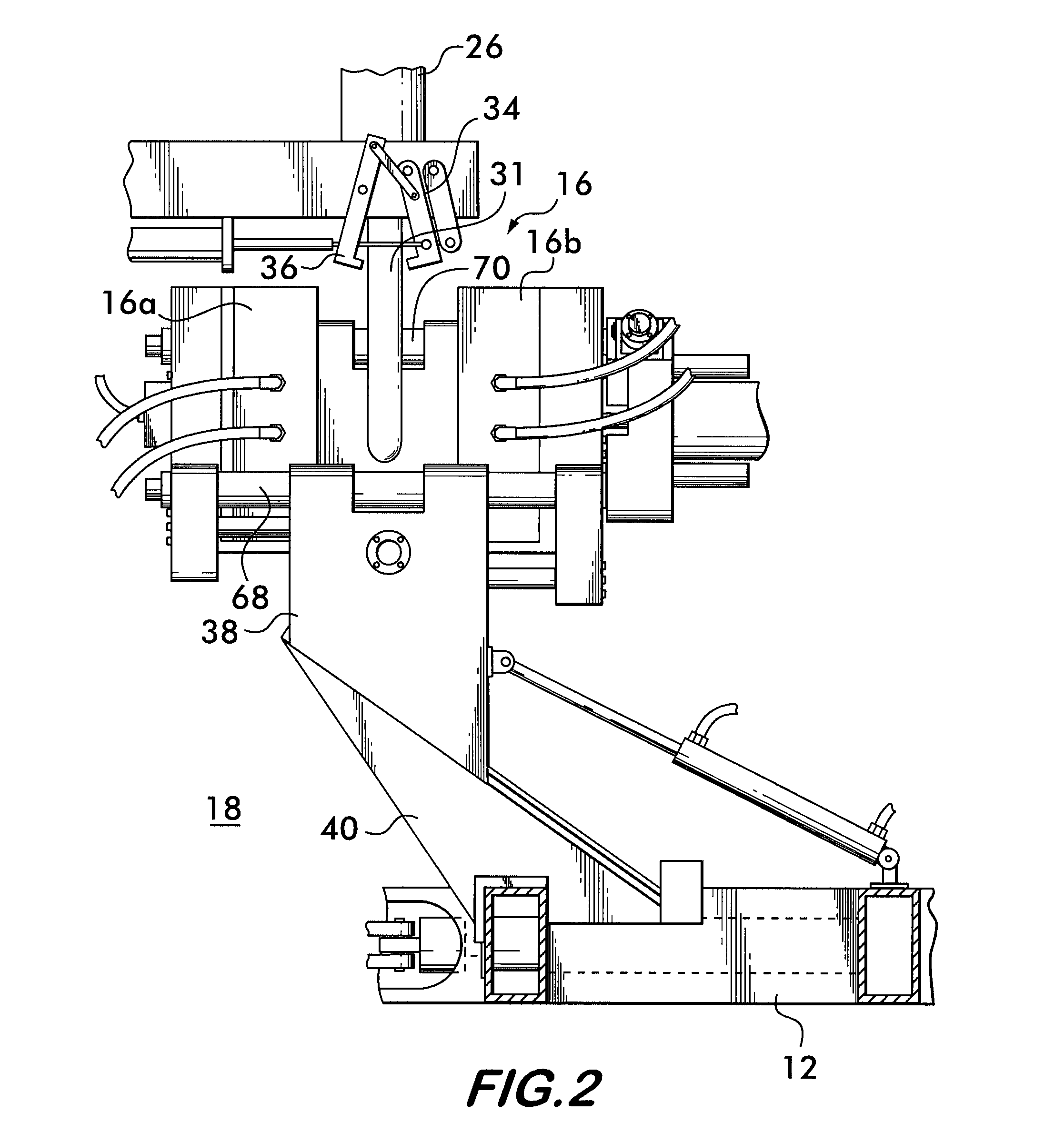
[0091]Improved blow molding machines 10 according to the invention provide several advantages over conventional devices. The use of a stationary flow head 26 reduces the potential for container defects and irregularities due to pendulum motion of the parison 31 as it is extruded. The rack-and-pinionassembly 78 ensures that the mold portions 16a and 16b move precisely and repeatably, along equidistant travel paths, and at the same closure rates, characteristics which are advantageous for container consistency and quality. The added container cooling time afforded by positioning the first station 18 at an acute angle 28 from the last station 22 ensures that containers 110 are sufficiently cured so that they may be handled without fear of damage upon removal from the mold 16. Furthermore, using soft, inflatable bladders 140 operating on the inside of the containers 110 to physically handle the containers 110 as they are released from the mold 16 helps to avoid damage, especially to the container neck region, which must maintain close tolerances for receiving spouts and sealing covers. In addition, positioning different molds 16 on the carriages 38 in an alternating or other sequence helps reduce machine down time by avoiding costly changeovers swapping molds16, and thereby increases productivity.
Problems solved by technology
Although such machines allow for high production rates of uniform containers, there are disadvantages in the various mechanisms and the method which, if eliminated, will result in more reliable production of high quality containers.
One such problem involves the moving flow head.
Motion of the flow head tends to amplify the swinging motion of the parison, which can lead to irregularities is and flaws in the containers as the mold halves close on a parison portion that is in a different position and orientation from one mold to the next.
Mold closing also affects the quality of the molded container.
Mold cooling also affects the container production.
Method used
Image
Click on the blue label to locate the original text in one second.
Reading with bidirectional positioning of images and text.
Examples
Embodiment Construction
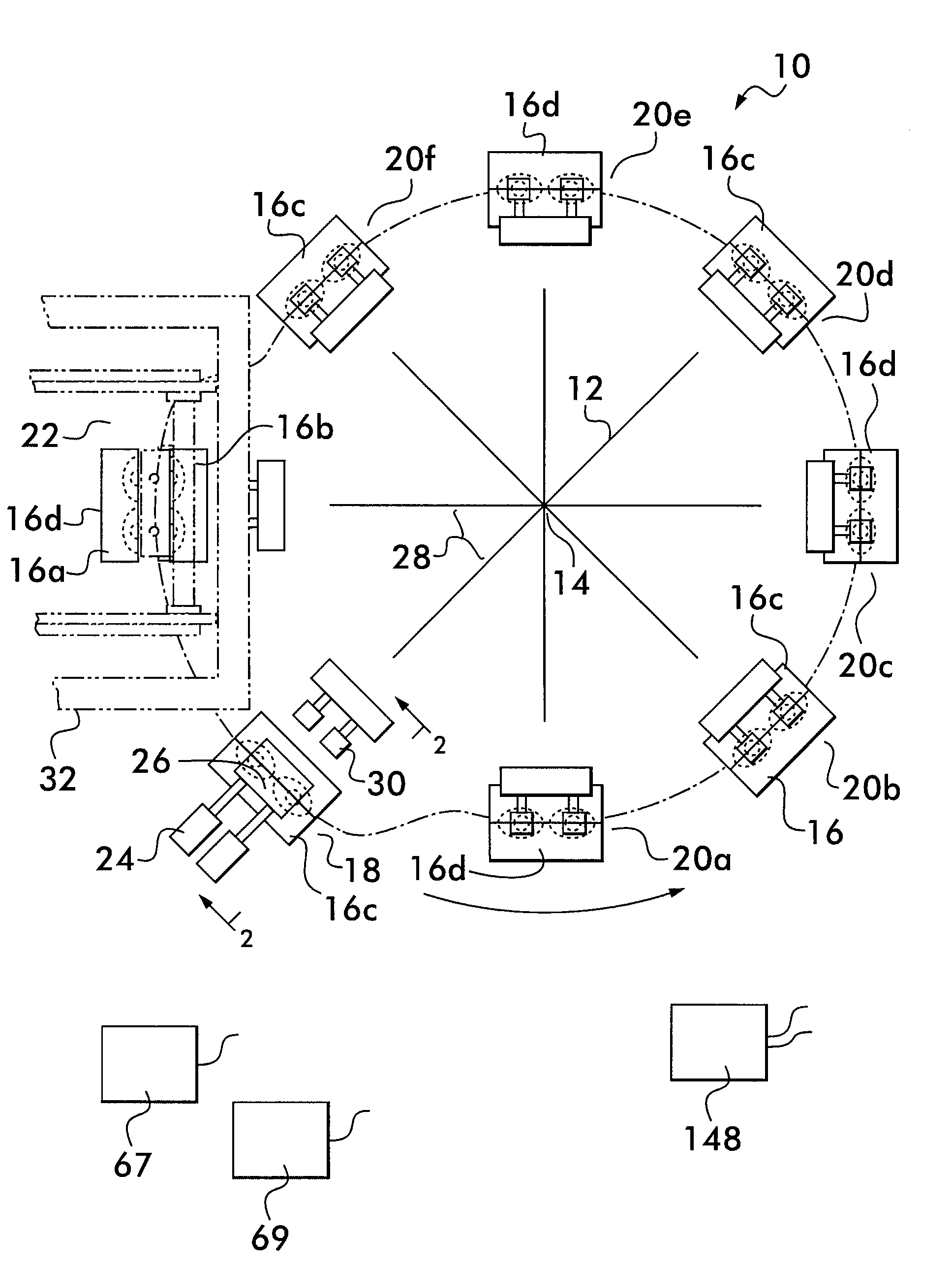
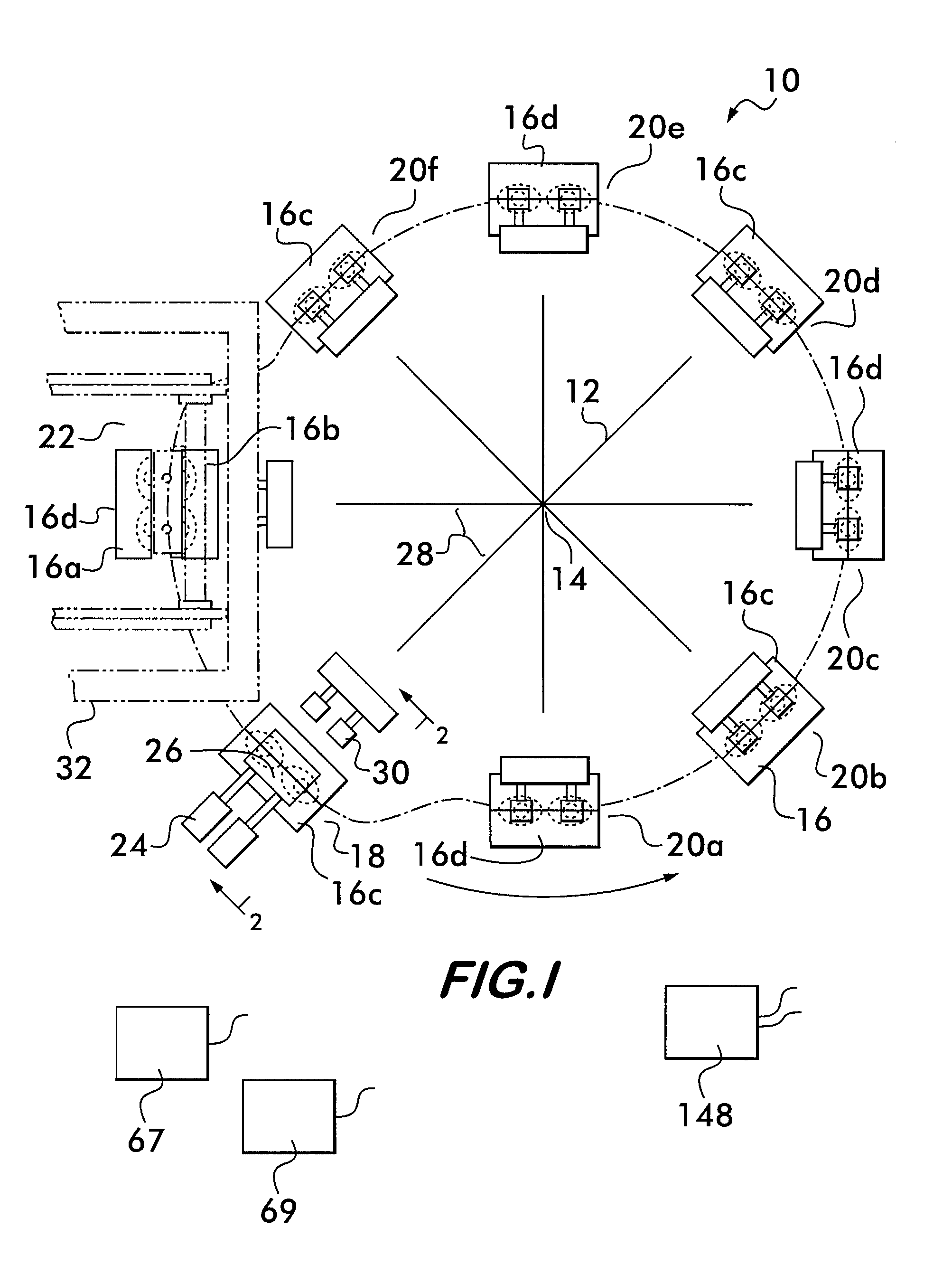
[0056]Referring now to the drawing, in which like reference numbers refer to like elements throughout the various figures that comprise the drawing, FIG. 1 shows a schematic plan view of an exemplary blow molding machine 10 according to the invention. Machine 10 comprises a turntable 12 rotatable by an electric motor (not shown) about an axis of rotation 14. Preferably, the turntable 12 is oriented horizontally and the axis of rotation 14 is substantially vertical.
[0057]One or more molds 16 are mounted on the turntable 12. Rotation of the turntable 12 counterclockwise positions each mold 16 successively at a plurality of stations including a first station 18, a plurality of intermediate stations 20a-20f, and a last station 22. The number of stations is equal to the number of molds 16 on the turntable 12, in this example, eight, although more or fewer stations are feasible. Each mold 16 comprises two mold portions 16a and 16b which are movable between an open configuration, as shown ...
PUM
Property
Measurement
Unit
acute angle
aaaaa
aaaaa
angle
aaaaa
aaaaa
shape
aaaaa
aaaaa
Abstract
A machine (10) for blow molding containers (110). The machine (10) has a stationary flow head (26) located above a turntable (12) with molds (16) mounted on carriages (38). The carriages (38) are mounted on ramps (40) and are raised to remove containers (110) and are lowered from the flow head (12) using a closed loop hydraulic system actuated by a cam. A double rack-and-pinionassembly (78) guides opening and closing of the molds (16) and a locking system having locking shafts (94, 96) engaging apertures (98, 100) in a cross head (74) with pivoting locking keys (102, 104) movable into alignment with the apertures (98, 100) prevents inadvertent mold opening. A container transfer device (32) has inflatable bladders (140) which engage the interior of the containers (110) to prevent damage. Augmented cooling of the containers (110) in the mold (16) is provided by positioning the flow head (26) at an acute angle (28) to the transfer device (32). Different molds (16) may be positioned on the turntable (12) in an alternating arrangement to facilitate production changeover.
Description
RELATED APPLICATION[0001]This application claims the benefit of priority to U.S. Provisional Patent Application Ser. No. 60 / 984,174, filed on Oct. 31, 2007, the contents of which are incorporated in this application by reference.FIELD OF THE INVENTION[0002]This invention relates to a machine and a method for blow molding containers from plastic resin.BACKGROUND OF THE INVENTION[0003]Containers holding liquids and bulk solids are economically manufactured in a continuous blow molding process, wherein a parison comprising a hollow tube of molten polymer resin is extruded continuously from a flow head. The parison is acted on by a series of moving molds, each of which is formed of mold halves which are moved sequentially to a position beneath the flow head in an open configuration. The flow head is positioned above the path of the molds and is moved downwardly toward each open mold as it arrives beneath the flow head to position a portion of the parison between the mold halves. The mol...
Claims
Application Information
Patent Timeline
Application Date:The date an application was filed.
Publication Date:The date a patent or application was officially published.
First Publication Date:The earliest publication date of a patent with the same application number.
Issue Date:Publication date of the patent grant document.
PCT Entry Date:The Entry date of PCT National Phase.
Estimated Expiry Date:The statutory expiry date of a patent right according to the Patent Law, and it is the longest term of protection that the patent right can achieve without the termination of the patent right due to other reasons(Term extension factor has been taken into account ).
Invalid Date:Actual expiry date is based on effective date or publication date of legal transaction data of invalid patent.
Patent Type & AuthorityApplications(United States)
InventorKWASNIEWSKI, WALDEMAR BOLESLAWSTRUPINSKI, SLAWOMIR IRENEUSZARTYMINSKI, PAWEL STEFANASSENDI, DARIUSZ PAWELBARTNIK, ROBERTKORDULA, DOMINIKKOWALCZK, ANDRZEJ TOMASZKOZAK, LESZEKROGACZEWSKI, ROBERT GRZEGORZSOLYGA, WOJCIECHWEGLOWSKI, MAREK WOJCIECHWOINSKI, GRZEGORZ JAROSLAWZAREBA, BOGDAN LUDWIK

