
Three-way optical device

a three-way optical and optical waveguide technology, applied in the field of wavelength division multiplexing (wdm) devices of optical fiber communication, can solve the problems of poor coupling efficiency, loss of signals, and difficult process for manufacturing gratings and optical waveguides

Inactive Publication Date: 2010-09-09
APAC OPTO ELECTRONICS
View PDF2 Cites 4 Cited by
  • Summary
  • Abstract
  • Description
  • Claims
  • Application Information

AI Technical Summary

Benefits of technology

[0009]The present invention is a three-way optical device, such that a loss of optical signals does not easily occur due to a poor coupling efficiency when a grating and an optical waveguide are used to couple or split the optical signals.
[0019]Therefore, the three-way optical device enables a photoelectric element to transmit an optical signal into the sleeve through penetrating an optical filter, and also enables an optical signal transmitted through the sleeve to be transmitted to a corresponding photoelectric element through penetrating an optical filter. The three-way optical device enables a photoelectric element to reflect an optical signal into the sleeve through an optical filter, and also enables an optical signal transmitted through the sleeve to be reflected to a corresponding photoelectric element through an optical filter. In the three-way optical device, since the optical signals reflected by the optical filter and that penetrating the optical filter have different wavelengths, the optical signals with different wavelengths are transmitted to the sleeve or corresponding photoelectric elements in reflecting and penetrating manners, without the problem of the loss of signals when the grating or the optical waveguide is used to couple the optical signals, thereby achieving the function of multiplexing or de-multiplexing the optical signals.

Problems solved by technology

However, in the fundamental constructions of the optical fiber communication network, optical fiber passive components have a high technical level, high product-added value, and low capital investment, and act as critical components for the optical fiber network, so as to be focused by the manufacturers from home and aboard.
However, the process for manufacturing the grating and the optical waveguide is not easy, and when the optical signals are coupled or split, the loss of signals usually occurs due to a poor coupling efficiency.

Method used


Image

  • Three-way optical device
  • Three-way optical device
  • Three-way optical device

Examples


first embodiment

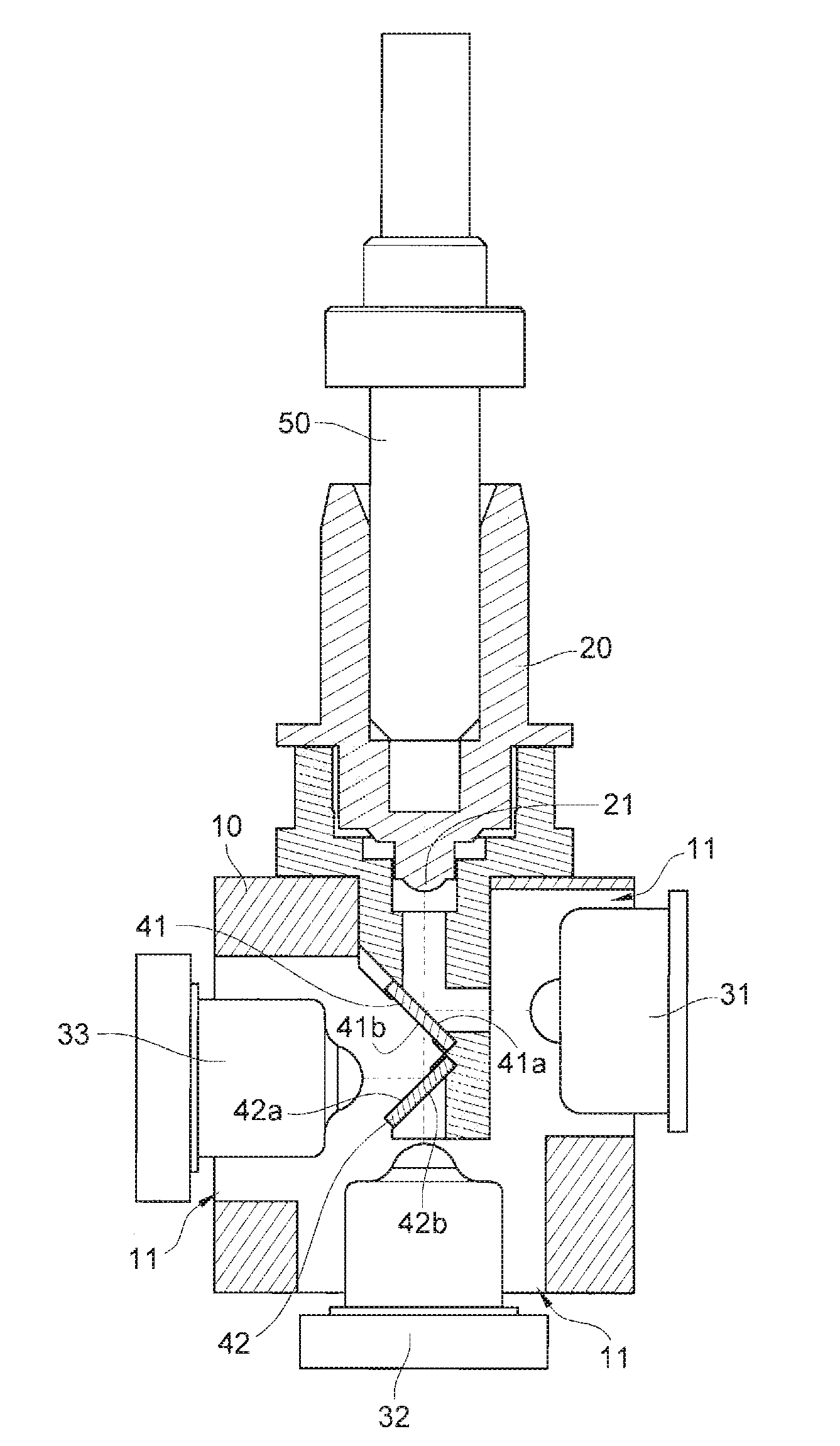
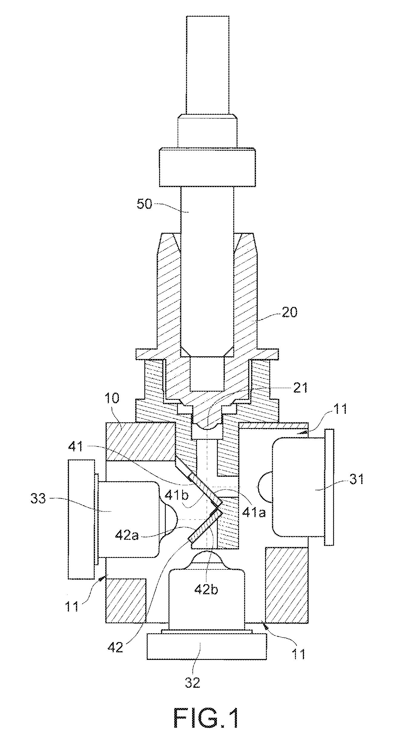
[0024]FIG. 1 is a schematic view of a three-way optical device according to the present invention.

[0025]Referring to FIG. 1, in this embodiment, the three-way optical device comprises a case 10, a sleeve 20, a plurality of photoelectric elements, and a plurality of optical filters 41 and 42.

[0026]In this embodiment, the photoelectric elements comprise an optical transmitter 31, an optical transmitter 32, and an optical transmitter 33.

[0027]For ease of description, in this embodiment, the number of the photoelectric elements is three, but the present invention is not limited thereto, and the number of the photoelectric elements may be one, two, or more than three.

[0028]For ease of description, in this embodiment, the number of the optical filters is two, but the present invention is not limited thereto, and the number of the optical filters may be one or more than two.

[0029]The case 10 has a plurality of openings 11. The plurality of openings 11 may be respectively opened on differen...

second embodiment

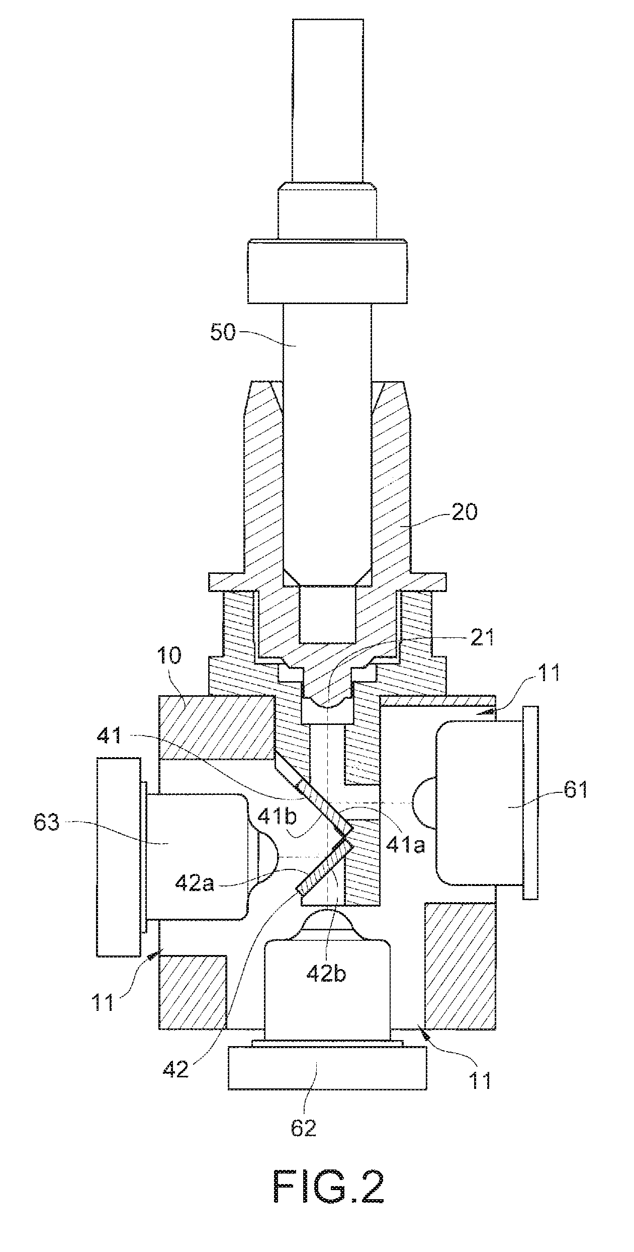
[0059]FIG. 2 is a schematic view of a three-way optical device according to the present invention.

[0060]Referring to FIG. 2, in this embodiment, the three-way optical device comprises a case 10, a sleeve 20, an optical receiver 61, an optical receiver 62, an optical receiver 63, and optical filters 41 and 42.

[0061]For ease of description, in this embodiment, the number of the optical receivers is three, but the present invention is not limited thereto, and the number of the optical receivers may be one, two, or more than three.

[0062]The case 10 has a plurality of openings 11 on surfaces thereof. The plurality of openings 11 may be respectively opened on corresponding surfaces of the case 10.

[0063]One end of the sleeve 20 is connected to one of the plurality of openings 11. The sleeve 20 comprises a lens 21. The lens 21 is located on one end of the sleeve 20 connected to the case 10.

[0064]The optical receiver 61 is correspondingly disposed in one of the plurality of openings 11.

[0065...

third embodiment

[0086]FIG. 3 is a schematic view of a three-way optical device according to the present invention. The detailed elements can be obtained with reference to the above-mentioned embodiments.

[0087]Referring to FIG. 3, in this embodiment, the three-way optical device comprises a case 10, a sleeve 20, an optical transmitter 31, an optical transmitter 32, an optical receiver 63, an optical filter 41, and an optical filter 42.

[0088]For ease of description, in this embodiment, the number of the optical transmitters is two, but the present invention is not limited thereto, and the number of the optical transmitters may be one, or more than two.

[0089]For ease of description, in this embodiment, the number of the optical receivers is one, but the present invention is not limited thereto, and the number of the optical receivers may be more than one.

[0090]The case 10 has a plurality of openings 11 on surfaces thereof. The plurality of openings 11 may be respectively opened on corresponding surfac...


PUM


Abstract

A three-way optical device includes a case, a sleeve connected to one of openings of the case, photoelectric elements disposed in one of the openings, and optical filters. Each photoelectric element is associated with an optical signal. Each optical filter is located in the case, corresponding to at least two photoelectric elements, and each optical filter is disposed on an optical path of optical signals associated with the at least two corresponding photoelectric elements. Each optical filter enables the optical signal associated with at least one photoelectric element to penetrate and reflects optical signals associated with the remaining corresponding photoelectric elements, in which the optical signals reflected by the optical filter and penetrating the same optical filter have different wavelengths. The optical signals having different wavelengths associated with the corresponding photoelectric elements are transmitted in a manner of penetrating the optical filters or being reflected by the optical filters.

Description

CROSS-REFERENCE TO RELATED APPLICATIONS[0001]This non-provisional application claims priority under 35 U.S.C. §119(a) on Patent Application No(s). 098107025 filed in Taiwan, R.O.C. on Mar. 4, 2009, the entire contents of which are hereby incorporated by reference.BACKGROUND OF THE INVENTION[0002]1. Field of the Invention[0003]The present invention relates to a wavelength division multiplexing (WDM) device of the optical fiber communication, and more particularly to a three-way optical device.[0004]2. Related Art[0005]Thanks to the advantages of high transmission speed, low noise, small weight, high security, and the like, optical fibers have become an indispensable transmission medium in the current communication network. With the development trend of the whole communication techniques and applications all over the world, the applications of the techniques associated with optical fibers have become indispensable transmission media for the optical fiber communication network, data tr...

Claims


Application Information

Patent Timeline
IPC IPC(8): H04J14/02H01L31/0232H01L31/09
CPCG02B6/4246
Inventor HUNG, TUAN YULI, CHANG YOUHSIEH, WEN CHIHCHEN, I HSIUCHIANG, LING YING
Owner APAC OPTO ELECTRONICS
Learn More