Electrochemical cell having quasi-bipolar structure

a cell and bipolar technology, applied in the direction of cell components, wound/folded electrode electrodes, sustainable manufacturing/processing, etc., can solve the problems of difficult to isolate the electrolyte of neighboring unit cells securely for a long time under various operation environments, current leakage occurs between the unit cells, etc., to achieve less pressure, simple structure, and effective isolation

Inactive Publication Date: 2010-09-09
KIMS TECHKNOWLEDGE
View PDF11 Cites 31 Cited by
  • Summary
  • Abstract
  • Description
  • Claims
  • Application Information

AI Technical Summary

Benefits of technology

[0039]In the electrochemical cell of the present disclosure, electrolyte injection holes are formed in a current collector extension part between negative and positive active material layers of a quasi-bipolar electrode and a sidewall of a hollow core around which the quasi-bipolar electrode is wound; an electrolyte isolation barrier wall is disposed at the current collector extension part of the quasi-bipolar electrode; and an electrolyte injection port is formed at a side surface of a case to inject electrolyte through the core. Therefore, a predetermined amount of electrolyte can be easily injected into each unit cell of electrochemical cells connected in series from the outside of the electrochemical cells, and a less pressure is applied to the electrolyte isolation barrier wall because the pressure levels inside the unit cells can be uniformly maintained, so that the electrolyte isolation barrier wall can be easily constructed and electrolyte can be isolated more effectively by the electrolyte isolation barrier wall. In addition, only one safety vent can be disposed at the electrolyte injection port formed at the side surface of the case instead of disposing a plurality of safety vents at the side surface of the case, so that the electrochemical cell can have a simple structure and the number of holes formed in the case can be reduced to minimize electrolyte leakage.
[0040]In the electrochemical cell of the present disclosure, a bead may be formed in the case in which an electrode assembly is accommodated to isolate electrolyte easily and prevent current leakage and corrosion.
[0041]In the electrochemical cell of the present disclosure, a safety vent having a membrane capable of transmitting gas may be used to seal an electrolyte injection part, and thus the electrochemical cell may have a slim shape.
[0042]In the electrochemical cell of the present disclosure, electrolyte injection holes corresponding to unit cells may be formed in the core to easily inject electrolyte into the unit cells and improve electrolyte isolation efficiency.
[0043]In the electrochemical cell of the present disclosure, wire holes may be formed in the core, and wires may be connected to the quasi-bipolar electrode to equalize voltages of unit cells and improve the reliability of the electrochemical cell.
[0044]In the electrochemical cell of the present disclosure, wire strips may be disposed on the core to easily assemble the electrochemical cell using a conductive adhesive.

Problems solved by technology

In the bipolar structure, if electrolytes of neighboring unit cells are not securely isolated, current leakage occurs between the unit cells, and the unit cells corrode easily.
Therefore, it is very difficult to isolate electrolytes of neighboring unit cells securely for a long time under various operation environments.
Another limitation of a bipolar electrochemical cell is that it is difficult to manufacture a high-capacity bipolar electrochemical cell.
The areas of electrodes should be increased to increase the capacity of a bipolar electrochemical cell; however, in this case, the structural strength of the bipolar electrochemical cell is reduced, and it is more difficult to isolate electrolytes of neighboring unit cells and inject electrolyte into the unit cells.
Furthermore, it is troublesome to assemble electrodes and separators into an electrochemical cell after electrolyte is filled between the electrodes and the separators.

Method used


Image

  • Electrochemical cell having quasi-bipolar structure
  • Electrochemical cell having quasi-bipolar structure
  • Electrochemical cell having quasi-bipolar structure

Examples


Embodiment Construction

[0101]Hereinafter, specific embodiments will be described in detail with reference to the accompanying drawings.

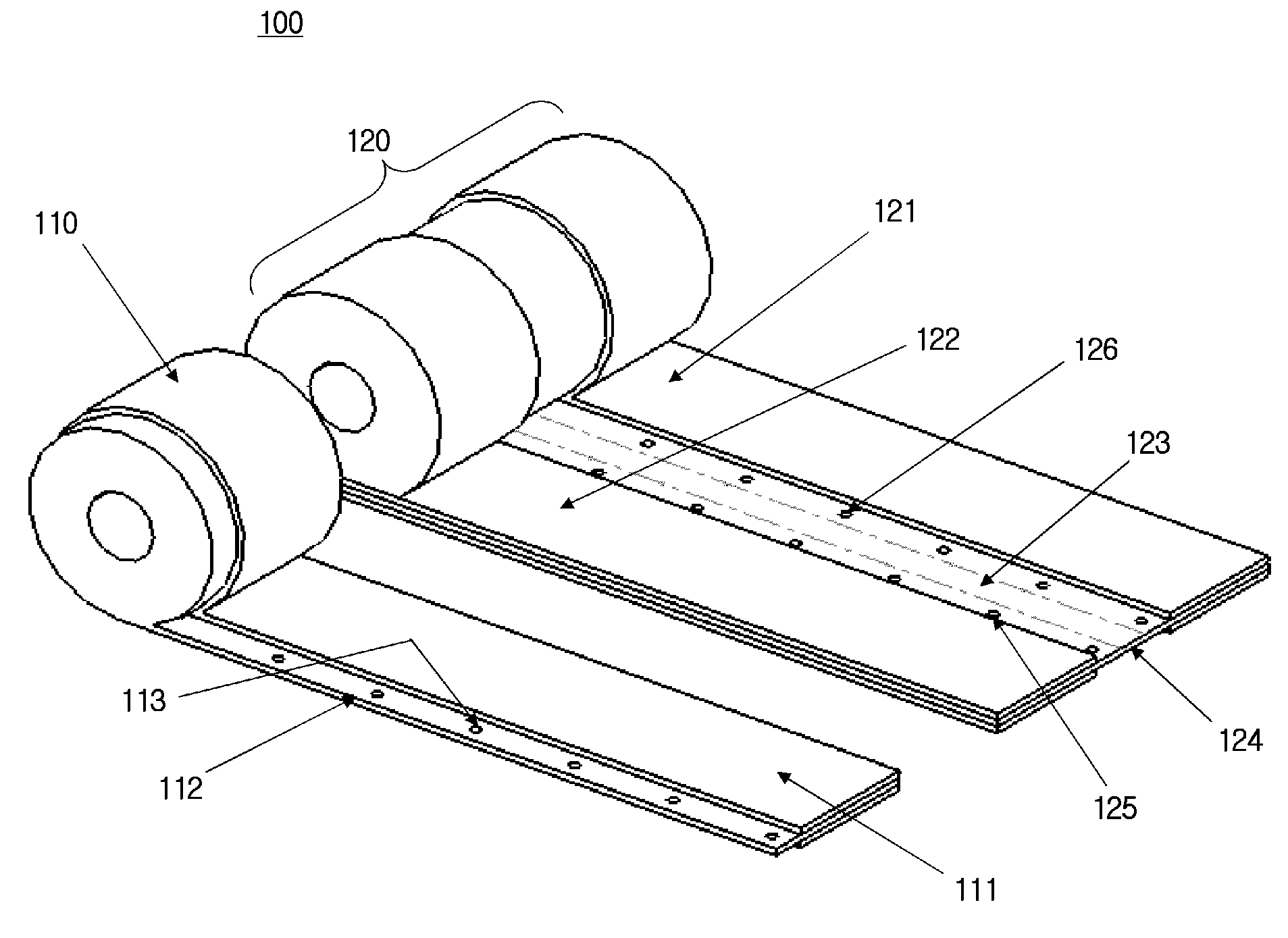
[0102]FIG. 8 is a perspective view illustrating electrodes of an electrochemical cell having a quasi-bipolar structure according to an exemplary embodiment.

[0103]Referring to FIG. 8, the electrochemical cell 100 of the current embodiment includes a mono polar electrode 110 and a quasi-bipolar electrode 120.

[0104]The mono polar electrode 110 includes a current collector 112 and active material layers 111 formed on the current collector 112 and having one polarity.

[0105]The quasi-bipolar electrode 120 includes a current collector 124, and positive and negative active material layers 121 and 122 that are formed on the current collector 124 and spaced apart from each other. An electrolyte isolation part 123 is formed at a current collector extension part between the positive and negative active material layers 121 and 122 for installing an electrolyte isolation barrier wall on...


PUM

PropertyMeasurementUnit
voltageaaaaaaaaaa
thicknessaaaaaaaaaa
thicknessaaaaaaaaaa

Abstract

An electrolyte injection hole is formed in a current collector extension part between negative and positive active material layers of a quasi-bipolar electrode, and another electrolyte injection hole corresponding to the electrolyte injection hole of the quasi-bipolar electrode is formed in a sidewall of a hollow core around which the electrode is wound, so as to easily inject a predetermined amount of electrolyte into each unit cell of an electrode assembly through an electrolyte injection port and the core. Therefore, simple, reliable, and easy-to-manufacture electrochemical cell can be provided.

Description

TECHNICAL FIELD[0001]The present disclosure relates to a modularized electrochemical cell having a quasi-bipolar structure, and in particular to, an electrochemical cell having a simple structure and improved reliability and productivity in a way of forming an electrolyte injection hole in a current collector extension part between negative and positive active material layers of a quasi-bipolar electrode, and another electrolyte injection hole a sidewall of a hollow core around which the quasi-bipolar electrode is wound, so as to easily inject a predetermined amount of electrolyte into each unit cell of an electrode assembly through an electrolyte injection port.BACKGROUND ART[0002]In general, electrochemical cells have a mono polar structure. Such a mono polar electrochemical cell includes a positive electrode composed of a positive active material formed on a current collector and a negative electrode composed of a negative active material formed on another current collector. Thes...

Claims


Application Information

Patent Timeline
Patent Type & Authority Applications(United States)
IPC IPC(8): H01M10/04H01M50/627
CPCH01G9/038H01G11/10H01G11/54H01G11/78H01M2/1229Y02E60/13H01M2/361H01M10/0413H01M10/0431H01M10/044H01M10/0587H01M2/266Y02E60/10H01M50/325Y02P70/50H01M50/627
Inventor KIM, SEONG MIN
Owner KIMS TECHKNOWLEDGE
Why Eureka
Try Eureka