

Check matrix generating method
a matrix and matrix technology, applied in the field of check matrix, can solve problems such as performance degradation generally, and achieve the effect of reducing the circuit scal
- Summary
- Abstract
- Description
- Claims
- Application Information
AI Technical Summary
Benefits of technology
Problems solved by technology
Method used
Image

Examples
first embodiment
[0039]Embodiments of a check-matrix generating method according to the present invention will be explained in detail below based on the drawings. It is noted that the present invention is not limited by these embodiments.
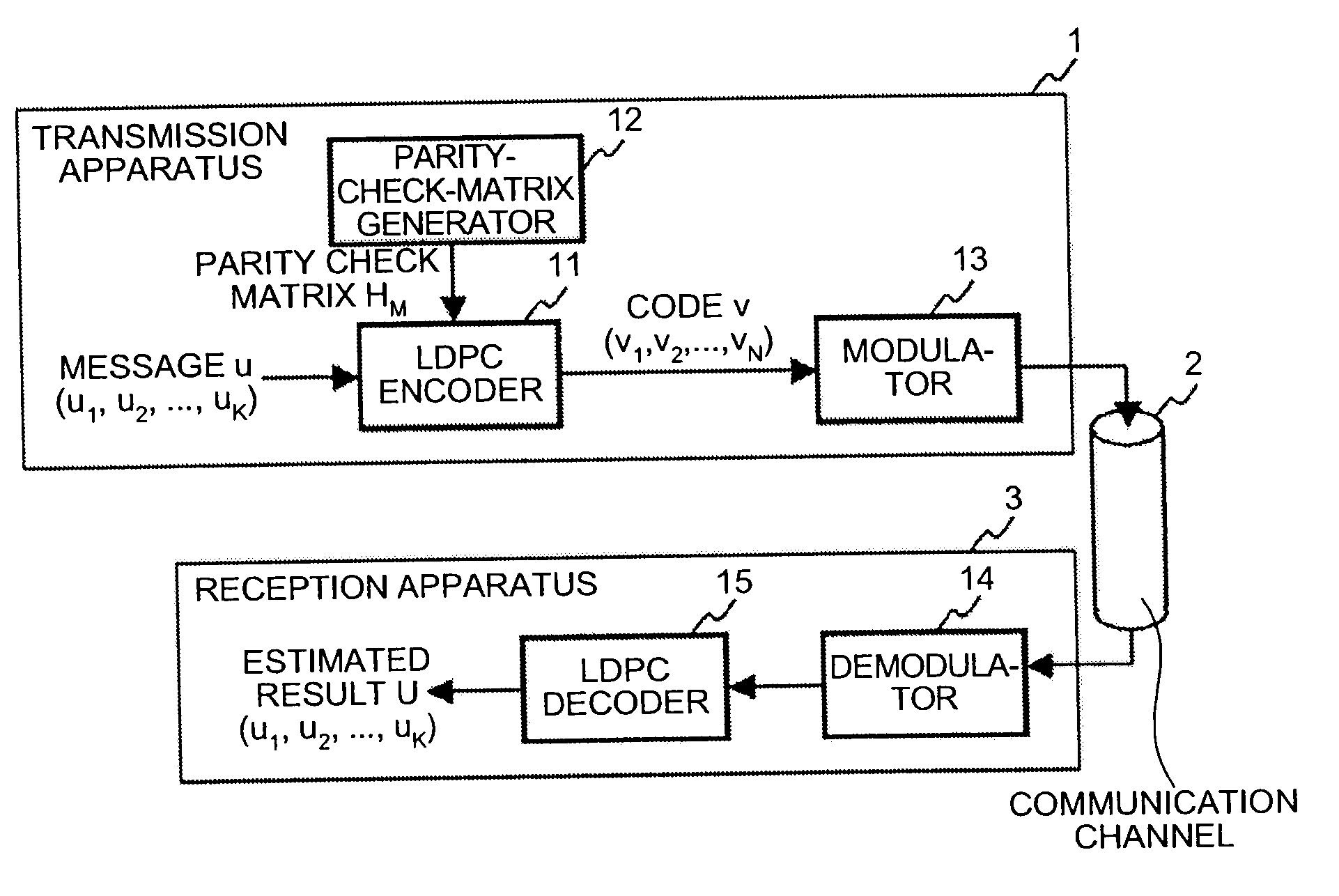
[0040]FIG. 1 is a diagram showing a configuration example of a communication system including a transmission apparatus and a reception apparatus according to a first embodiment of the present invention. In the figure, a transmission apparatus 1 includes an LDPC encoder 11, a parity-check-matrix generator 12, and a modulator 13. A communication channel 2 is an information transmission channel, typically such as a wireless transmission network and an optical transmission network. A reception apparatus 3 includes a demodulator 14 and an LDPC decoder 15.
[0041]Incidentally, it is not always necessary for the communication channel 2 to enable bidirectional communications, and thus, for example, the configuration may be such that information is transmitted by directly tran...
second embodiment
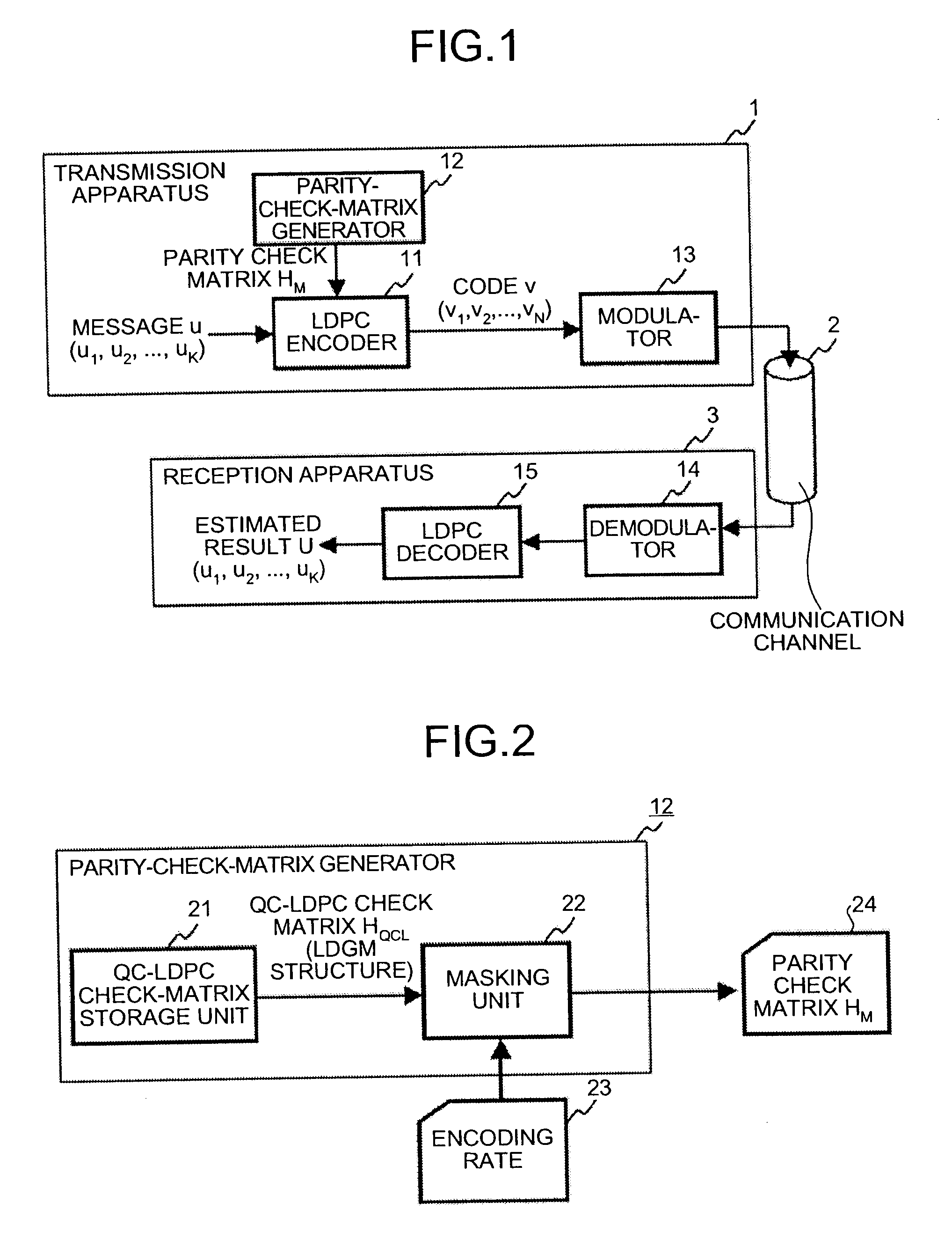
[0088]The parity check-matrix generating method according to the first embodiment deals with the encoding rate ⅓, and can also deal with a case where the encoding rate is any other value. The parity check-matrix generating method for dealing with up to an encoding rate ⅕ will be explained below. It is noted that the configuration of the communication system is the same as that shown in FIG. 1, and how to configure the parity-check-matrix generator is the same as that as shown in FIG. 2.
[0089]Here, if the number of data bits is 32 and the encoding rate 23 is ⅕, the quasi-cyclic matrix HQC is 128 (row index j is 0 to 127)×32 (column index l is 0 to 31). In this case, the masking unit 22 masks the quasi-cyclic matrix HQCL with O-elements of the mask matrix Z with 128-row×32-column.
[0090]After the mask matrix Z is generated, the irregular parity check matrix HM output from the masking unit 22 can be represented as Equation (18) using the mask matrix Z with 128-row×32-column, the quasi-c...
third embodiment
[0102]Subsequently, the configuration to set a lower limit of the encoding rate smaller than ⅙ will be explained below. In the communication system according to the first embodiment and the second embodiment, the lower limit of the encoding rate is desirably set to any value from ⅓ to ⅙. When the encoding rate equal to or less than the rate is to be achieved, achievement thereof using repeated transmission is more advantageous than the configuration based on the method mentioned in the first and the second embodiments because satisfactory performance is obtained.
[0103]FIG. 4 represents the case where the encoding rate up to 1 / 10 is prepared using the code configuration method according to the first and the second embodiments, and also represents a case where the repeated transmission of a code explained hereinafter is used (the above-mentioned code is used when an encoding rate is up to ⅕, and the repeated transmission is used when an encoding rate is smaller than that). Note that t...
PUM
 Abstract
Description
Claims
Application Information