[0012]A further advantageous embodiment relates to such a shaft-hub assembly, wherein the expansion element and the corresponding inner peripheral region of the hub are constructed in such a manner that due to the
coefficient of friction between the expansion element and the inner peripheral region and due to a displacement angle between the displaced areas of the expansion element, at the radial ends of which the outer peripheral region of the expansion element is disposed, and the inner peripheral region of the expansion element, a self-locking effect of the expansion element is created in the hub. The displaced areas of the expansion element can be preferably formed, for example, as finger-like extensions, wherein their ends form the outer peripheral area and wherein the sides of the finger-like extensions, which are opposite to the outer peripheral region, are attached on an expansion element base. Such a finger-like extension is deformed in the context of the elastic deformation essentially in the area of the point of attachment on the expansion element base, so that the remaining portion of the finger-like extension is pivoted as a displaced area of the expansion element by the displacement angle in an essentially undeformed state. Herein, the region of the finger-like extension which is referred to as the outer peripheral region, carries out the described combined movement in the axial and radial directions. The term self-locking means that, as a force is applied to the axial pin in the axial direction against an introduction direction of the axle pin, a
normal force resulting from this force is created between the outer peripheral region of the expansion element and the inner peripheral region of the hub, which, taking the
coefficient of friction between the outer peripheral region of the expansion element and the inner peripheral region of the hub into consideration, results in a frictional force which is greater than the force applied to the axle pin in the axial direction against the introduction direction of the axle pin (not taking the frictional force into account which is created by the
spring force of the expansion element). By means of this configuration, the axle pin together with the expansion element can be pushed into the hub and is fixed in the inserted position in the hub in a direction against the introduction direction. Alternatively or additionally, fixing can be effected by selecting the material
pairing between the material of the expansion element and the material of the hub in such a manner that the outer peripheral region of the expansion element can penetrate the surface of the inner peripheral region of the hub during expansion, so that the self-locking effect is replaced or reinforced by an
interlocking engagement. Herein, the outer peripheral region of the expansion element is preferably formed with a sharp edge in such a manner that penetration into the surface of the inner peripheral region of the hub is facilitated.
[0023]A further advantageous embodiment relates to a
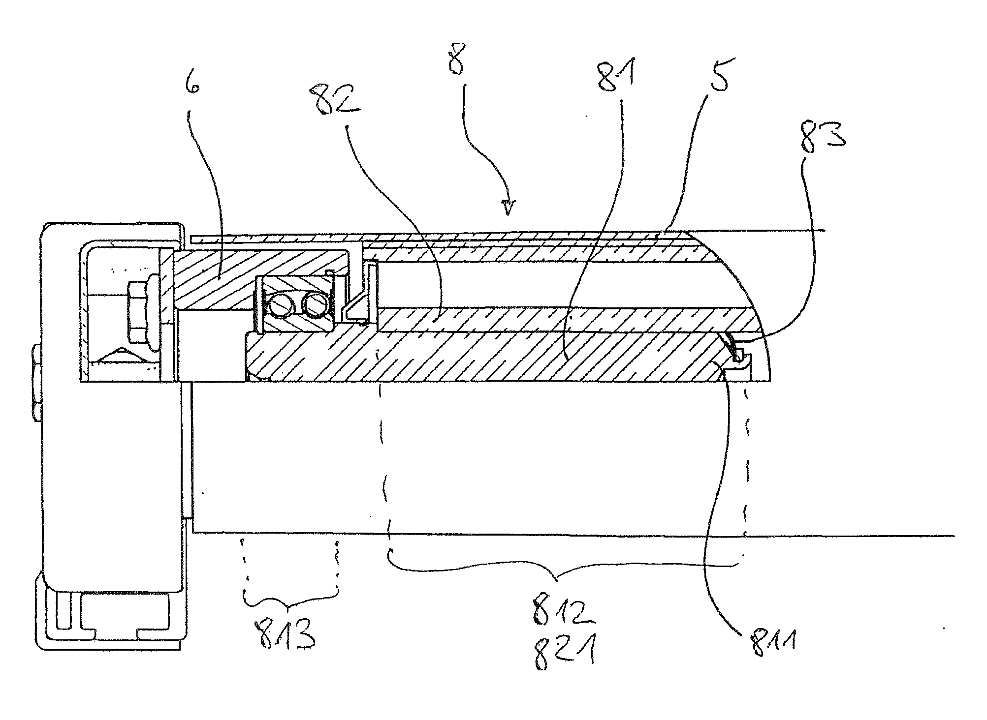
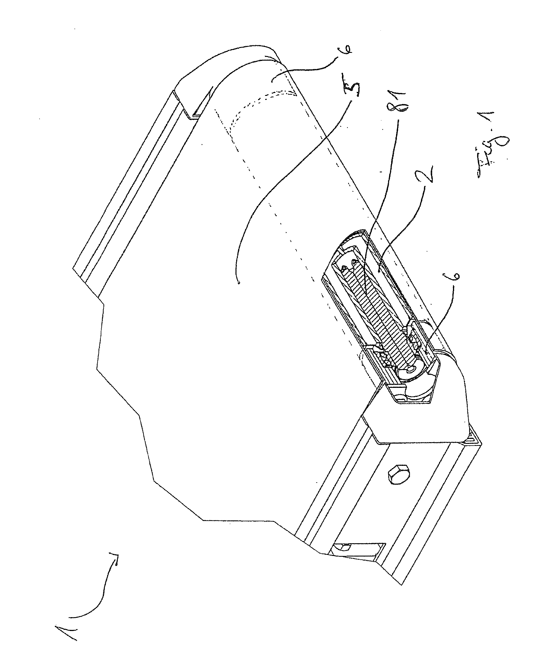
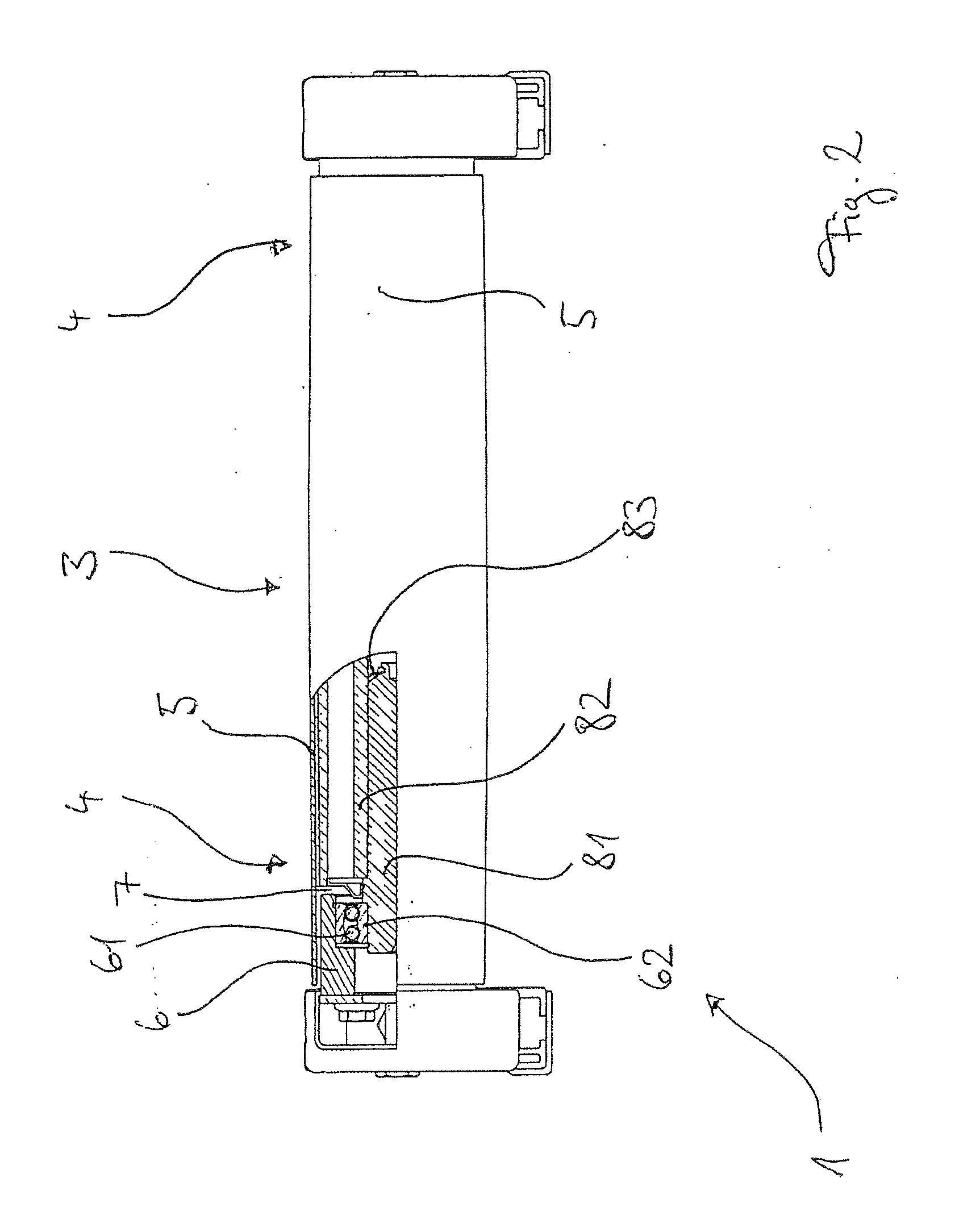
conveyor system, wherein the conveyor roller at least on one side is supported in a bearing cup having a
radius which, at least in an angle of wrap of the
conveyor belt, is essentially equal to or slightly smaller than the
radius of the conveyor roller in the axial end region of the conveyor roller, wherein the conveyor belt is wider than the length of the conveyor roller in the axial direction, and wherein the conveyor belt is arranged on the conveyor roller in such a manner that the gap between the conveyor roller and the bearing cup is covered by the conveyor belt. The angle of wrap depends on the degree of redirecting of the conveyor belt on the conveyor roller. If the conveyor roller is used as a return roller at the end of a conveyor belt, the angle of wrap can be 180° or more. In the case of a conveyor roller which is used between the ends of a conveyor belt, the angle of wrap can be just a point on the circumference in cross-section, or can be in the form of a line extending in the longitudinal direction of the conveyor roller. The bearing cup is used to
mount the conveyor roller in a frame of the
conveyor system. Herein, the gap which would arise between the frame and the conveyor roller in conventional bearings is displaced toward the roller center of the conveyor roller. Surprisingly, it has become apparent that depending on the configuration of the conveyor cup, or the conveyor roller, the relative movement between the conveyor belt, which is carried across the surface of the conveyor cup in a sliding manner, does not lead to undesirable wearing of the conveyor belt. This can be explained by the fact that, in particular with a larger diameter of the conveyor roller in the roller end region of the conveyor roller with respect to the diameter of the bearing cup, the belt tension is negligible in the region of the bearing cup. This effect can also be seen if the
radius of the bearing cup in the region of wrap is essentially equal to the radius of the conveyor roller in the roller end region, if the conveyor roller has a crowned configuration, that is it has a greater diameter in the center region of the roller than in the roller end region. Independently of the configuration of the radii or diameters of the bearing cup and the conveyor roller, wear phenomena can be reduced or even eliminated also by a particularly
smooth surface finish of the bearing cup and / or a suitable choice of materials for the bearing cup and the conveyor belt. Preferably, the bearing cup is made of steel. Herein, the conveyor roller is supported by one bearing cup on each of both sides.


