Electrical junction box for vehicle

a technology for electric junction boxes and vehicles, applied in the direction of high current circuit adaptations, electric devices, transportation and packaging, etc., can solve the problems of wiring boards, difficult to reduce a difference in area, interference with the downsizing of the whole electrical junction box, etc., to reduce the number of terminals for connecting, reduce the size of the whole structure, and reduce the effect of controlling the circui

Inactive Publication Date: 2010-09-16
SUMITOMO WIRING SYST LTD
View PDF1 Cites 19 Cited by
  • Summary
  • Abstract
  • Description
  • Claims
  • Application Information

AI Technical Summary

Benefits of technology

[0008]In view of the above problems, an object of the present invention is to provide an electrical junction box for a vehicle that can effectively restrain a control circuit from being subject to a heat adverse effect from a power distribution circuit, can downsize a whole structure, and can reduce the number of terminals for connecting the circuits to each other.

Problems solved by technology

a. It is difficult to reduce a difference in area between the wiring board that constitutes the power distribution circuit and the ECU board that constitutes the control circuit.
This difference in area will interfere with downsizing of the whole of the electrical junction box.
This difference in area will become great as the power distribution circuit becomes complicated.
It will be difficult to effectively contain both boards in a single casing assembly as the difference in area becomes great.
In result, it will become difficult in downsizing of the casing assembly.
Such increase of the number of the terminals will invite upsizing of a connector including the terminals, thereby interfering with enhancement of reliability in connection.

Method used


Image

  • Electrical junction box for vehicle
  • Electrical junction box for vehicle
  • Electrical junction box for vehicle

Examples


Embodiment Construction

[0016]Preferable embodiments of an electrical junction box for a vehicle in accordance with the present invention will be described below by referring to the drawings.

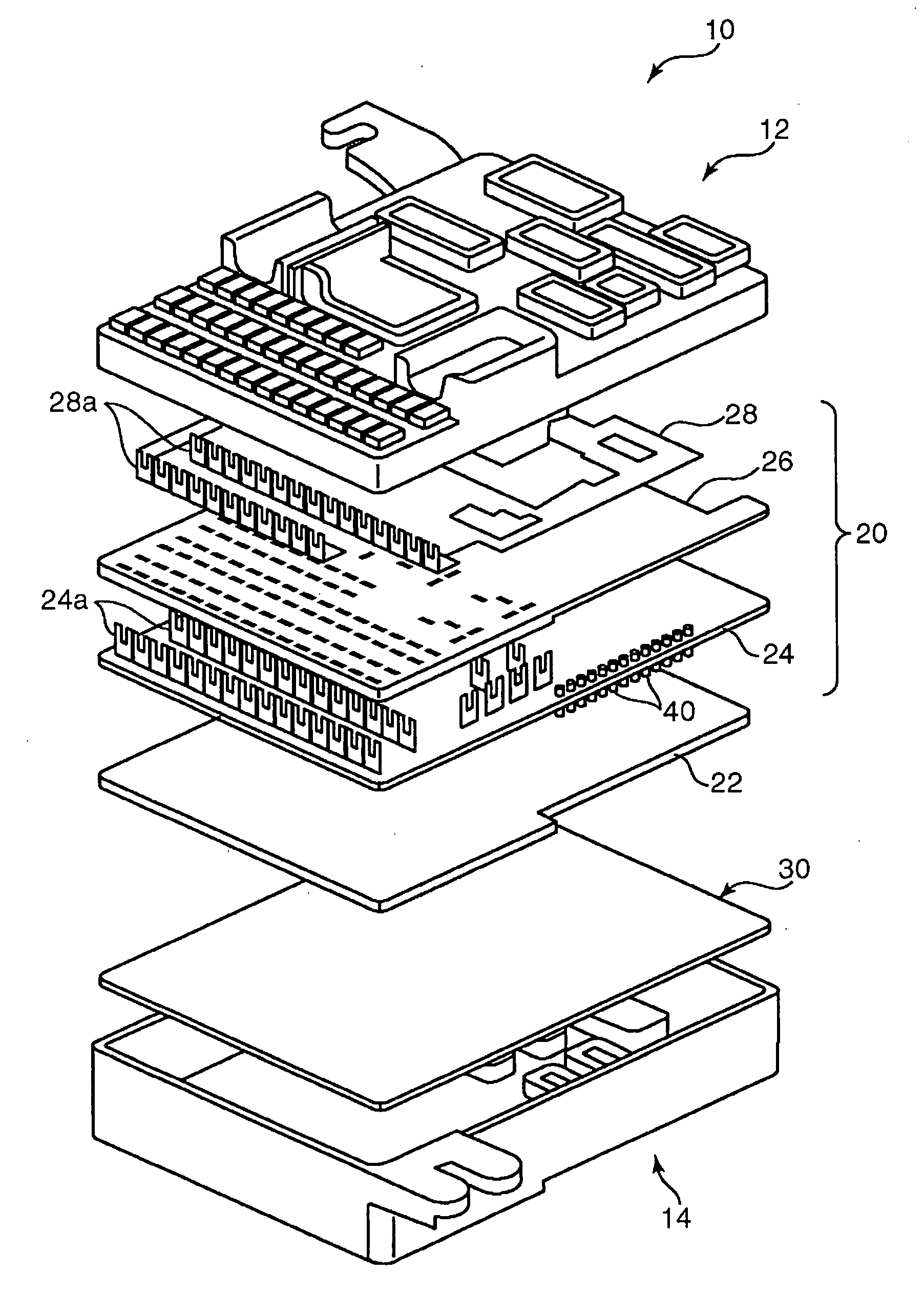
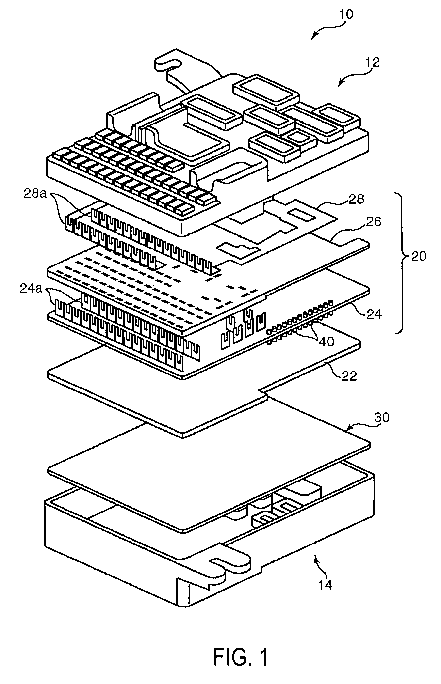
[0017]FIG. 1 is an exploded perspective view of an embodiment of an electrical junction box 10 for a vehicle in accordance with the present invention. The electrical junction box 10 includes an upper casing 12, a lower cover 14, a power distribution unit 20, and a circuit board 30. When the upper casing 12 and lower cover 14 are coupled to each other in a vertical direction, they constitute the electrical junction box 10. The power distribution unit 20 is laminated on the circuit board 30 in a plate thickness direction so that they are contained in a casing assembly.

[0018]The power distribution unit 20 is constructed by laminating an insulation plate 22, a wiring board 24, an insulation plate 26, and a bus bar 28 upward in order. The wiring board 24 includes a board body made of glass fiber, synthetic resin, or the lik...


PUM


Abstract

An object of this invention is to provide an electrical junction box for a vehicle that can effectively restrain a control circuit from being subject to heat adverse effect from to a power distribution circuit, can downsize the whole structure, and can reduce the number of terminals for connecting the circuits to each other. The electrical junction box for a vehicle comprises a power distribution unit for constituting a part of the power distribution circuit, and a circuit board. A board body of the circuit board is divided into a power distribution circuit region Ap and a control circuit region Ac by a border line BL across the circuit board body. The control circuit is incorporated in the control circuit region Ac. The power distribution circuit region Ap is provided with a power distribution circuit having a current specification smaller than that of the power distribution circuit on the power distribution unit.

Description

FIELD OF THE INVENTION[0001]This invention relates to an electrical junction box for a vehicle that constitutes a power distribution circuit for distributing a power source mounted on a vehicle such as a motor vehicle to a plurality of vehicle-mounted loads.BACKGROUND OF THE INVENTION[0002]Heretofore, an electrical junction box for a vehicle has been known which includes a power distribution circuit for distributing a power source for a vehicle to a plurality of vehicle-mounted loads, and a control circuit for controlling an on-off action of switching elements (for example, a relay switch, and a transistor) included in the power distribution circuit.[0003]For example, an electrical junction box disclosed in Patent Document 1 includes a wiring board for constituting the power distribution circuit, and an ECU board for controlling an on-off action of a semiconductor relay packed on the wiring board. The ECU board includes a board body, and a plurality of L-shaped terminals projecting ...

Claims


Application Information

Patent Timeline
Patent Type & Authority Applications(United States)
IPC IPC(8): B60L1/00
CPCB60R16/0238B60R16/0239H05K2201/10303H05K2201/09972H05K2201/10053H05K1/0263
Inventor SUGIMURA, YOSHIAKIHOSONO, TSUYOSHI
Owner SUMITOMO WIRING SYST LTD
Why Eureka
Try Eureka