Bi-Silicate Matrix Coating for a Display
a bi-silicate matrix and display technology, applied in the field of color display, can solve the problems of affecting the appearance of the display,
- Summary
- Abstract
- Description
- Claims
- Application Information
AI Technical Summary
Problems solved by technology
Method used
Image

Examples
example 1
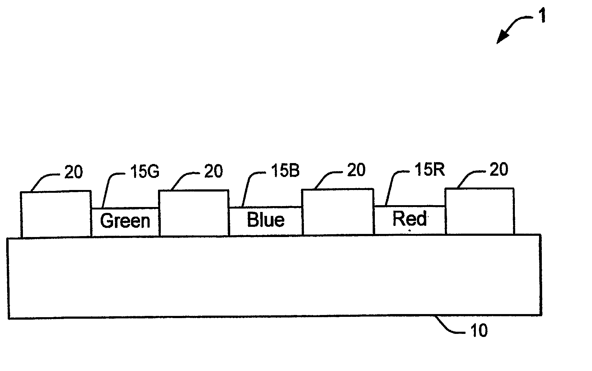
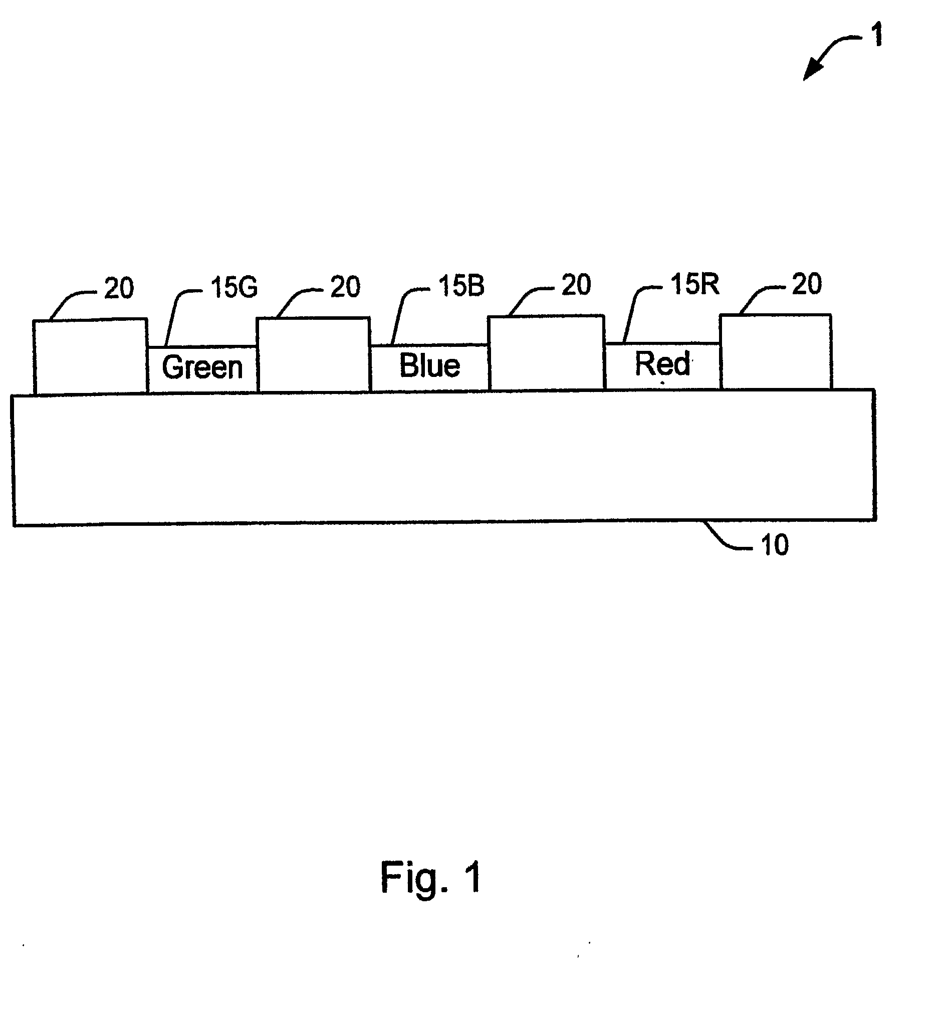
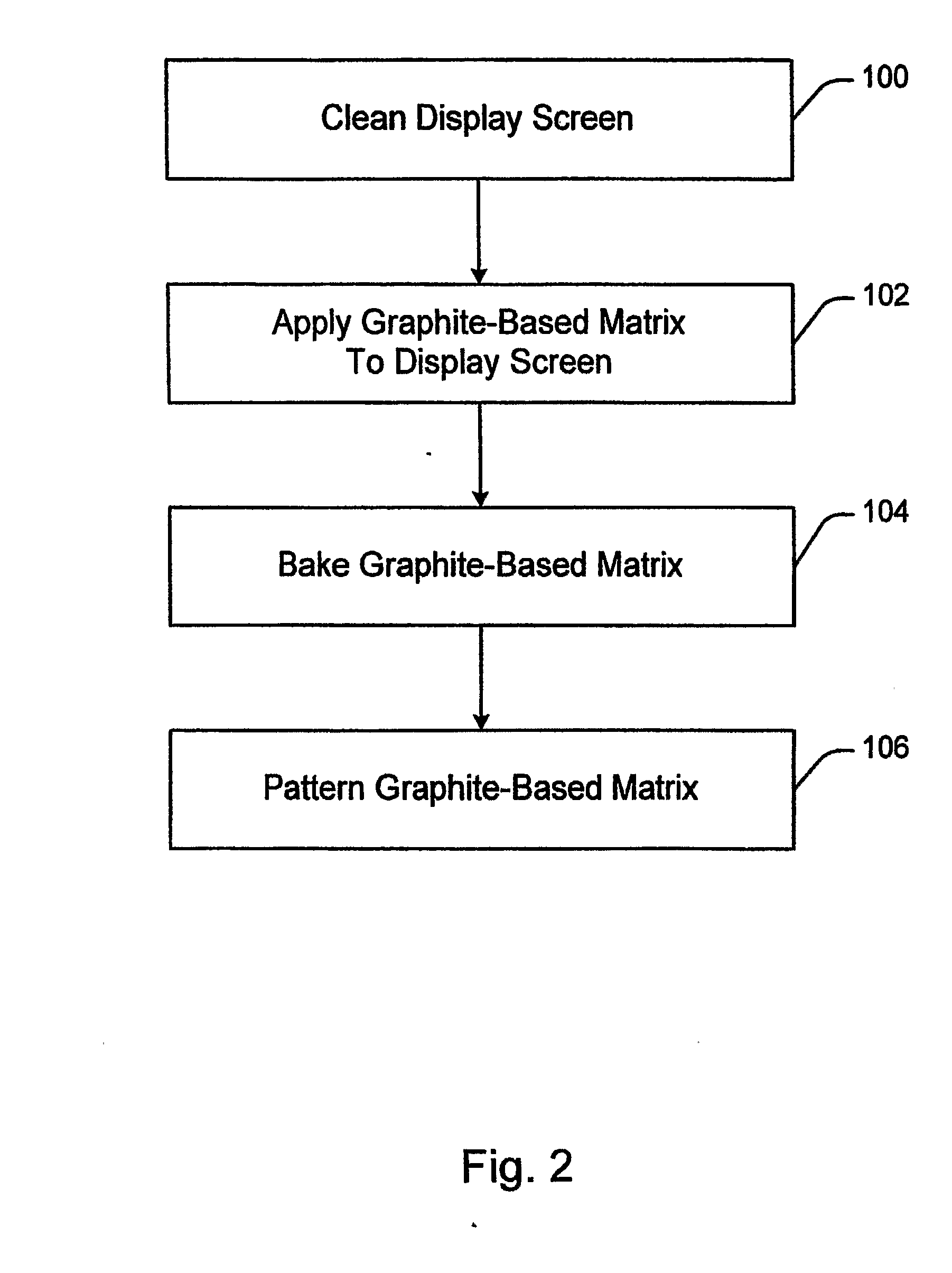
[0013]An exemplary aqueous graphite-based matrix solution is formed by mixing 14.4 grams of Kasil 2135 potassium silicate (commercially available from PQ Corporation, Valley Forge, Pa.), 9.4 grams of J sodium silicate (commercially available from PQ Corporation, Valley Forge, Pa.), 100 grams Electrodag 1530 graphite dispersion (commercially available from Acheson Colloids Company, Port Huron, Mich.) and in 128.9 grams of deionized water. The aqueous graphite-based matrix solution is further mixed on a jar roller for more than about 30 minutes. After mixing the graphite-based matrix composition should be applied to a display screen within about 24 hours to avoid agglomeration.
[0014]A coating formed from the graphite-based matrix composition of Example 1 was tested for adhesion. No failure occurred at the glass / coating interface or within the body of the coating.
example 2
[0015]An exemplary aqueous graphite-based matrix solution is formed by mixing 8.1 grams of Kasil 2135 potassium silicate (commercially available from PQ Corporation, Valley Forge, Pa.), 5.25 grams of J sodium silicate (commercially available from PQ Corporation, Valley Forge, Pa.), 100 grams Electrodag 1530 graphite dispersion (commercially available from Acheson Colloids Company, Port Huron, Mich.) and in 83.75 grams of deionized water. The aqueous graphite-based matrix solution is further mixed on a jar roller for more than about 30 minutes. After mixing the graphite-based matrix composition should be applied to a display screen within about 24 hours to avoid agglomeration.
[0016]A coating formed from the graphite-based matrix composition of Example 2 was tested for adhesion. No failure occurred at the glass / coating interface or within the body of the coating.
example 3
[0017]An exemplary aqueous graphite-based matrix solution is formed by mixing 5.84 grams of Kasil 2135 potassium silicate (commercially available from PQ Corporation, Valley Forge, Pa.), 11.98 grams of J sodium silicate (commercially available from PQ Corporation, Valley Forge, Pa.), 100 grams Electrodag 1530 graphite dispersion (commercially available from Acheson Colloids Company, Port Huron, Mich.) and in 111.31 grams of deionized water. The aqueous graphite-based matrix solution is further mixed on a jar roller for more than about 30 minutes. After mixing the graphite-based matrix composition should be applied to a display screen within about 24 hours to avoid agglomeration.
[0018]A coating formed from the graphite-based matrix composition of Example 3 was tested for adhesion. No failure occurred at the glass / coating interface or within the body of the coating.
PUM
 Abstract
Description
Claims
Application Information
 - R&D
- Intellectual Property
- Life Sciences
- Materials
- Tech Scout
- Unparalleled Data Quality
- Higher Quality Content
- 60% Fewer Hallucinations
Browse by: Latest US Patents, China's latest patents, Technical Efficacy Thesaurus, Application Domain, Technology Topic, Popular Technical Reports.
© 2025 PatSnap. All rights reserved.Legal|Privacy policy|Modern Slavery Act Transparency Statement|Sitemap|About US| Contact US: help@patsnap.com