Array antenna apparatus including multiple steerable antennas and capable of avoiding affection among steerable antennas

a technology of array antennas and steerable antennas, which is applied in the direction of antenna details, electrically short antennas, antennas, etc., can solve the problems of increasing the correlation between antenna elements and the degradation of transmission quality, and achieve the effect of preventing undesirable preventing resonances in the control lin

Active Publication Date: 2010-09-16
PANASONIC INTELLECTUAL PROPERTY CORP OF AMERICA
View PDF3 Cites 22 Cited by
  • Summary
  • Abstract
  • Description
  • Claims
  • Application Information

AI Technical Summary

Benefits of technology

[0018]In order to solve the above-described problems of the prior art, an array antenna apparatus of the present invention is configured as follows. Each parasitic antenna element has a space at the middle of the parasitic element, and is provided with a pair of rectifier elements (e.g., PIN diodes) connected in series such that their anode terminals oppose to each other, and the rectifier elements are connected through control lines to bias voltage supply means (controller) such that their anode terminals are connected to an on / off terminal of the bias voltage supply means and their cathode terminals are connected to a GND terminal of the bias voltage supply means. In addition, inductors with a certain inductance are inserted to each control line at predetermined intervals, at portions of the control line that are electromagnetically coupled to a steerable antenna (preferably, inserted at three points in total, i.e., a point on the control line that is closest to an adjacent steerable antenna, and two points on the control line each remote from the closest point by a predetermined distance). The distances between the inductors are preferably set to a length different from an integral multiple of one-quarter of an operating wavelength for communication, e.g., set to a length shorter than one-quarter of the operating wavelength.
[0019]When a voltage from the controller is lower than an operating voltage of a diode, the diode is equivalent to a series connected circuit of small capacitance and impedance, and accordingly, the parasitic antenna element does not affect antenna radiation, thus resulting in omnidirectional radiation. On the other hand, when a voltage from the controller is higher than the operating voltage of the diode, the diode becomes conductive, and thus, the parasitic antenna element acts as a reflector. By using this circuitry, even when operating in a high-frequency range where variable reactance elements are not operable, it is possible to change a MIMO antenna's directivity.
[0020]Moreover, the inductors inserted to the control lines prevent undesirable resonances in the control lines. By setting the distances between the inductors to be shorter than one-quarter of the operating wavelength, the resonance frequency of the control lines becomes higher than the operating frequency. By using such a configuration, it is possible to prevent that resonances in the control lines affect the directivity of an adjacent antenna.

Problems solved by technology

In this case, there is a problem of degradation in transmission quality caused by increases in the correlations between antenna elements, unless addressing this situation by, e.g., sufficiently separating the antenna elements from one another, or tilting the respective antenna elements in different directions to make a combination of different polarizations.

Method used


Image

  • Array antenna apparatus including multiple steerable antennas and capable of avoiding affection among steerable antennas
  • Array antenna apparatus including multiple steerable antennas and capable of avoiding affection among steerable antennas
  • Array antenna apparatus including multiple steerable antennas and capable of avoiding affection among steerable antennas

Examples


first preferred embodiment

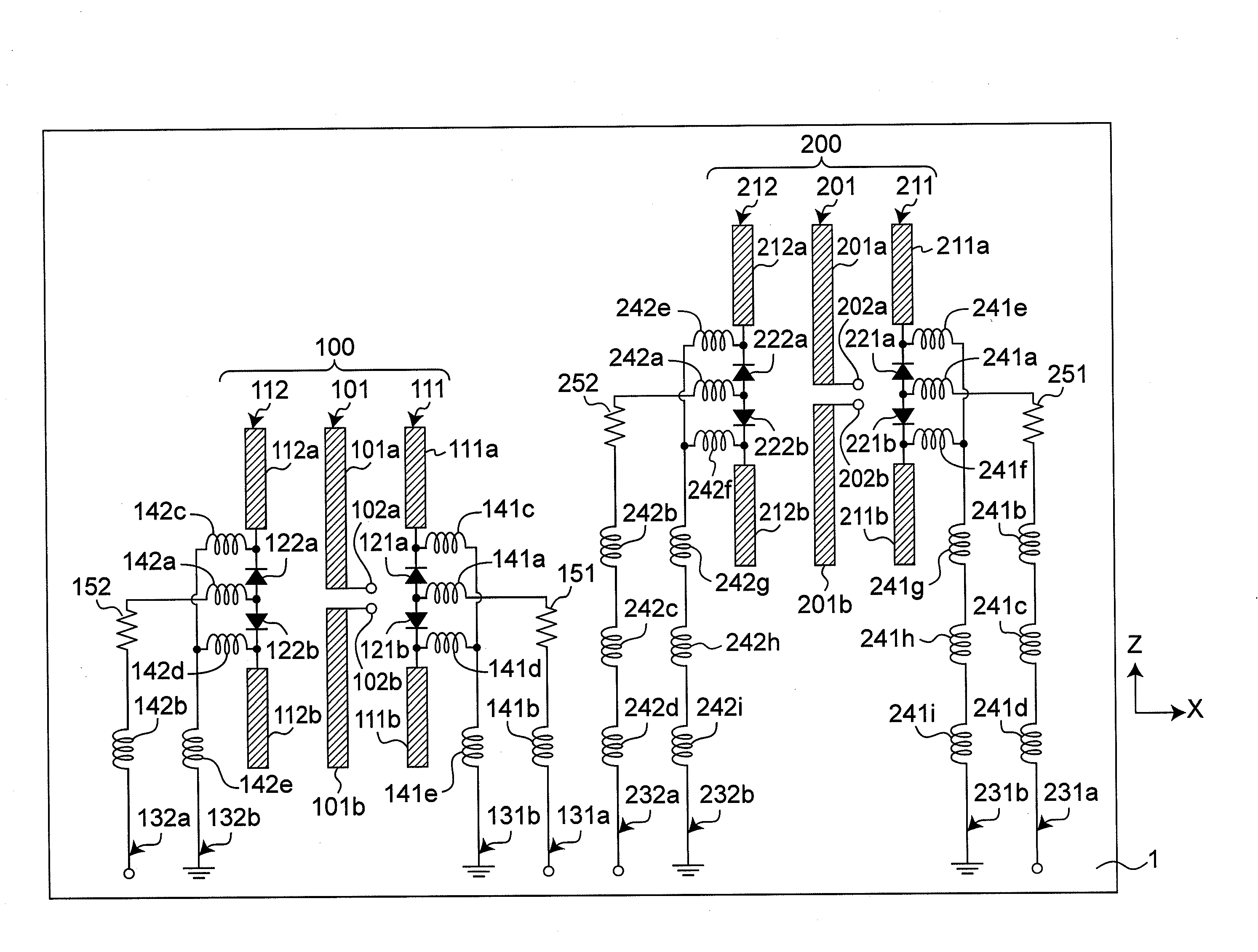
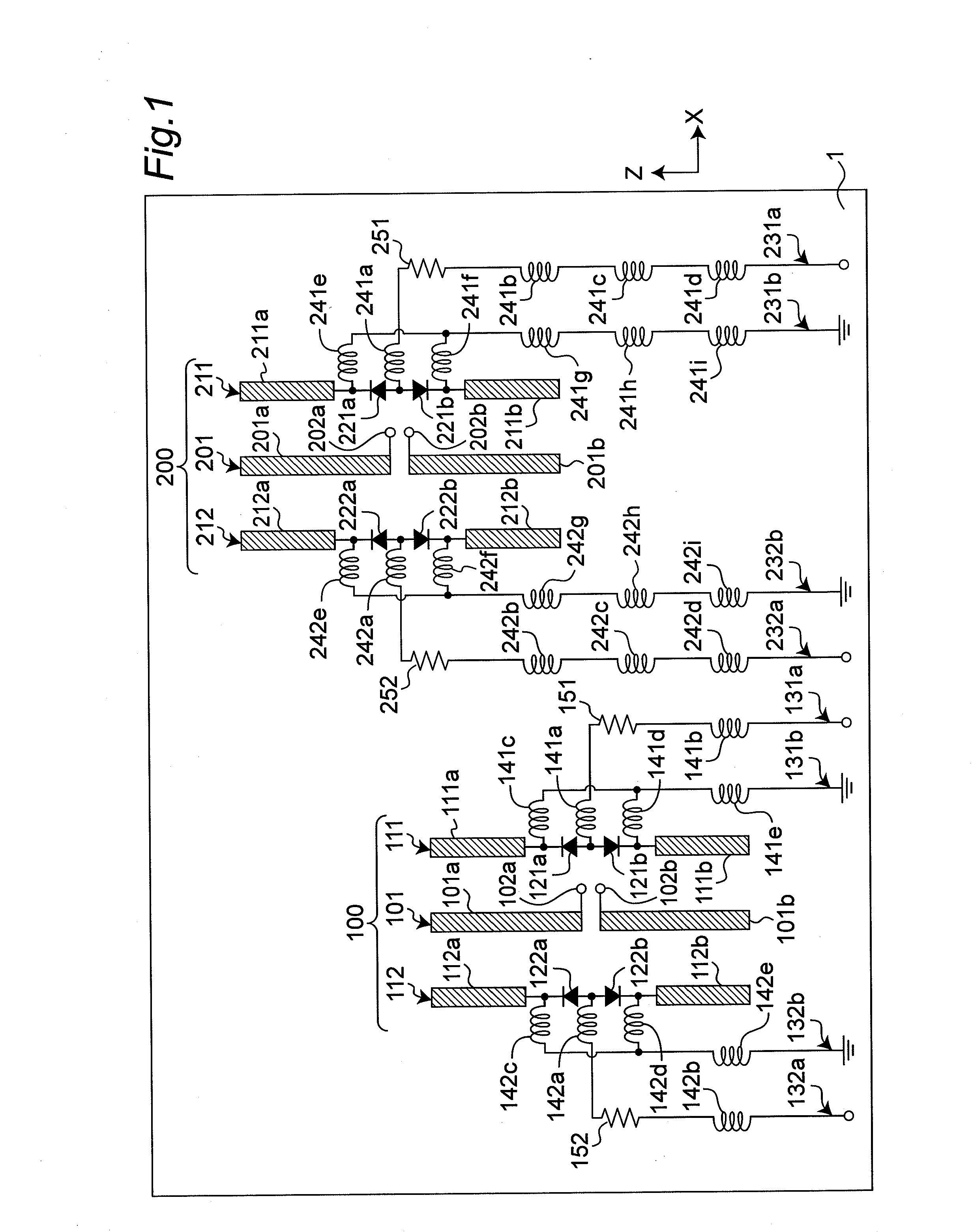
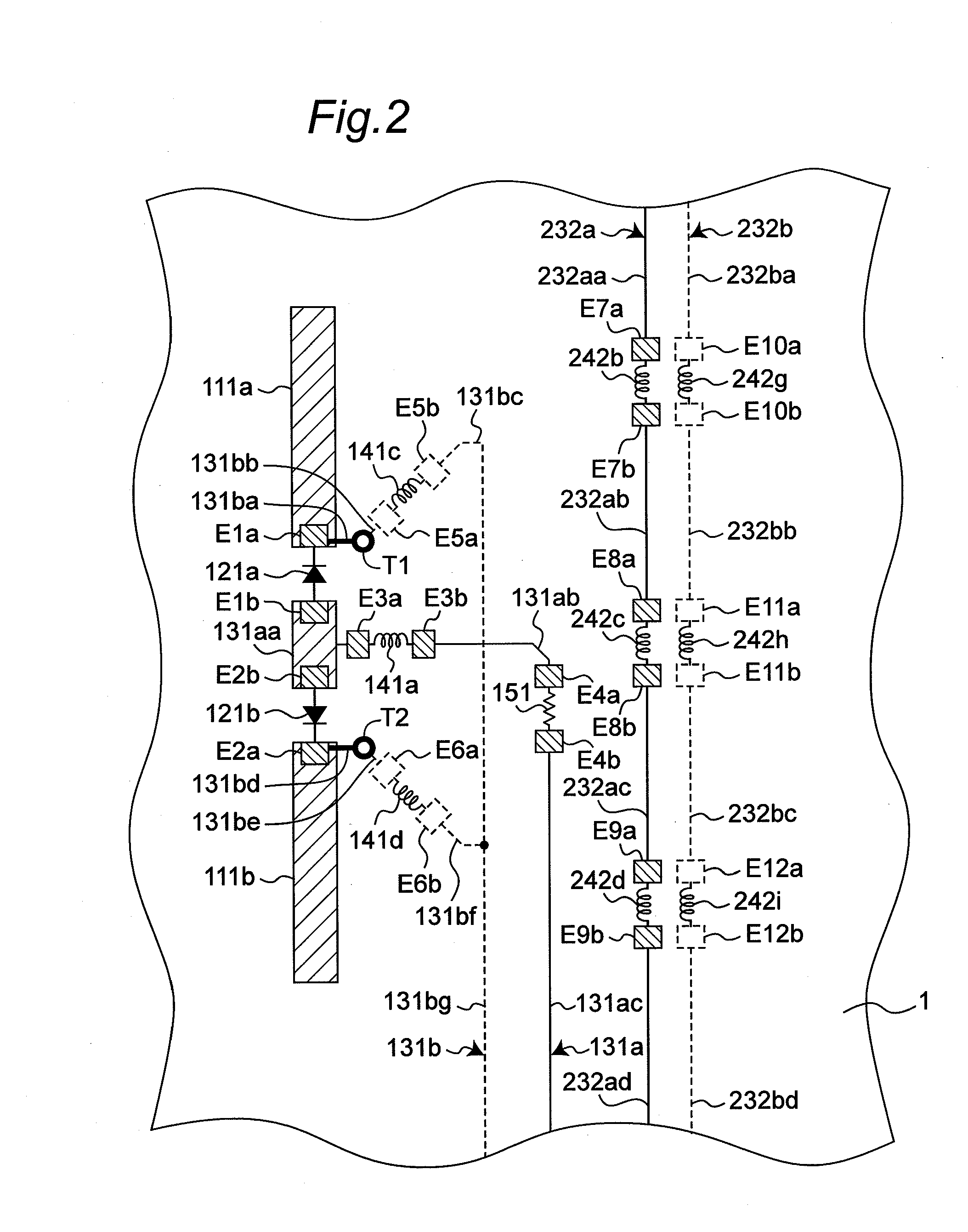
[0046]FIG. 1 is a plan view showing a schematic configuration of an array antenna apparatus according to a first embodiment of the present invention. FIG. 2 is a detailed view of a part of FIG. 1 in phantom. An array antenna apparatus according to the present embodiment includes two sets of steerable antennas 100 and 200 on a printed wiring board 1. Note that the XYZ coordinate is used as shown in FIG. 1, and for a Y-axis, a direction from front to back of FIG. 1 is assumed to be a positive direction.

[0047]The steerable antenna 100 includes one half-wave dipole antenna element 101 as an radiating antenna element, and two parasitic antenna elements 111 and 112. The dipole antenna element 101 includes two strip radiating conductor elements 101a and 101b, each formed as a conductor pattern on the printed wiring board 1. The radiating conductor elements 101a and 101b oppose to each other with a space therebetween, and are located along a straight line. Feeding points 102a and 102b are r...

second preferred embodiment

[0060]FIG. 7 is a top view showing a schematic configuration of an array antenna apparatus according to a second embodiment of the present invention. FIGS. 8 to 10 are plan views respectively showing schematic configurations of printed wiring boards 1a, 1b, and 1c of FIG. 7. The array antenna apparatus according to an embodiment of the present invention is not limited to the one in which antennas are formed within a plane of one printed wiring board 1 as in the first embodiment, but may have a three dimensional configuration in which three or more parasitic antenna elements are provided so as to surround an radiating antenna element.

[0061]As shown in FIG. 7, an array antenna apparatus according to the present embodiment includes two sets of steerable antennas 100A and 200A, on the three printed wiring boards 1a, 1b, and 1c provided in parallel with each other. The steerable antenna 100A includes one half-wave dipole antenna element 101 as an radiating antenna element, and four paras...


PUM


Abstract

A steerable antenna includes an radiating antenna element and parasitic antenna elements. Each of the parasitic antenna elements is provided with a pair of PIN diodes. On each of control lines connecting the PIN diodes to a controller, inductors are provided at predetermined intervals on portions of the control line electromagnetically coupled to another steerable antenna. The intervals for providing the inductors is set to such a length that substantially no resonance occurs in a section of the control line between the inductors at an operating frequency of the steerable antenna.

Description

TECHNICAL FIELD[0001]The present invention relates to a steerable array antenna apparatus capable of electrically steering its beam directions. More particularly, the present invention relates to a circuitry for controlling directivity of the array antenna apparatus.BACKGROUND ART[0002]In recent years, devices applying wireless techniques, such as wireless LANs complying with IEEE 802.11a / b / g standards, and Bluetooth, have been rapidly spreading. IEEE 802.11a and IEEE 802.11g specified the data transmission rate of 54 Mbps, and recently, active researches and developments have been done on wireless schemes for achieving higher transmission rates.[0003]As one of techniques for increasing transmission rates of wireless communication systems, a MIMO (Multi-Input Multi-Output) communication system has received wide attention. This is a technique for increasing transmission capacity and improving communication speed by providing both the transmitter and the receiver with multiple antenna...

Claims


Application Information

Patent Timeline
Patent Type & Authority Applications(United States)
IPC IPC(8): H01Q3/00
CPCH01Q1/2291H01Q1/528H01Q21/062H01Q9/285H01Q3/44
Inventor SHINKAI, SOTARONOGUCHI, WATARUYURUGI, HIROYUKINAGOSHI, MASAHIKOSHIOTSUKI, AKIHIKO
Owner PANASONIC INTELLECTUAL PROPERTY CORP OF AMERICA
Why Eureka
Try Eureka