Multi-joint robot and control program thereof

a multi-joint robot and control program technology, applied in the direction of computer control, program control, instruments, etc., can solve the problems of not being able to follow the corresponding components of the current state vector of the end link, and the inability of the joint to be controlled based on the target drive quantity, so as to ease the overloaded state

Inactive Publication Date: 2010-09-16
TOYOTA JIDOSHA KK
View PDF7 Cites 44 Cited by
  • Summary
  • Abstract
  • Description
  • Claims
  • Application Information

AI Technical Summary

Benefits of technology

[0041]According to the present teaching, a multi-joint robot which, in a case where any of the joints becomes overloaded, makes the end link of the robot follow the target state vector as accurately as possible, while easing the overloaded state can be realized. According to this multi-joint robot, in a case where any of joints become overloaded, the follow-up performance of the end link to the target state vector is secured in the predetermined order of having higher priority among the components of the target state vector. Therefore, even if any of the joints becomes overloaded, the follow-up performance of the end link (follow-up performance to the components of the target vector, of the components of the current state vector of the end link) may be achieved as for the components of the target state vector that are important, for the work that the multi-joint robot performs. As the result, the multi-joint robot may continue the work as far as possible, even though any of the joints become overloaded.

Problems solved by technology

When a joint becomes overloaded and the torque limiter is activated, the joint may not be controlled based on the target drive quantity.
Therefore, if any one of the joints becomes overloaded and that joint becomes incapable of following its target drive quantity, it becomes impossible for some of the components of the current state vector of the end link follow the corresponding components of the target state vector.

Method used


Image

  • Multi-joint robot and control program thereof
  • Multi-joint robot and control program thereof
  • Multi-joint robot and control program thereof

Examples


first embodiment

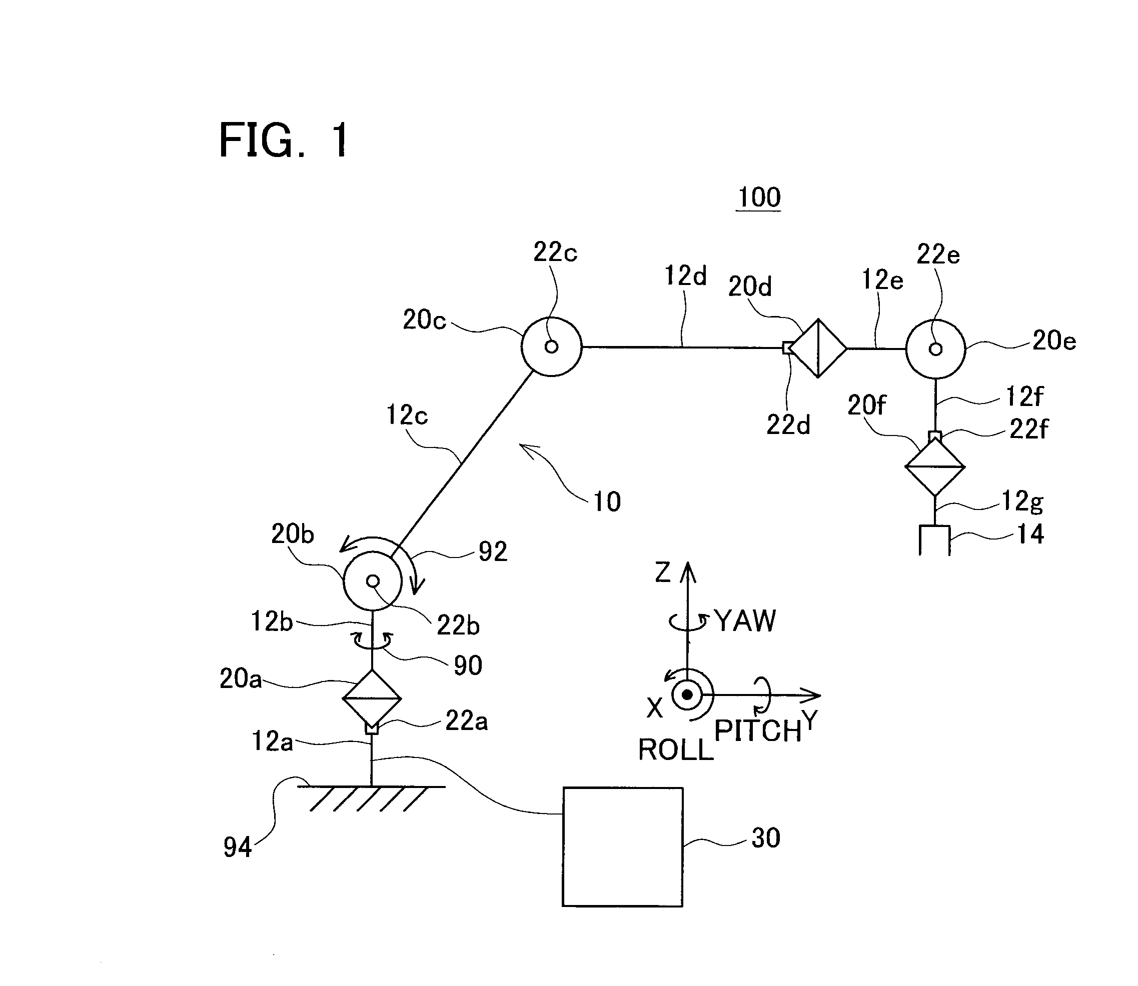
[0061]The multi joint robot of the first embodiment will be described with reference to the drawings. FIG. 1 shows a schematic view of a multi joint robot 100. The multi joint robot 100 includes a robot mechanism 10 (multi-joint robot mechanism) and a controller 30. FIG. 1 illustrates the robot mechanism 10 with a skeleton diagram showing the coupling structure of the joints and links. The multi-joint robot 100 in this embodiment holds a glass filled with water (not illustrated) located at an initial position with a gripper 14, and performs a glass moving work to place the glass at an intended position with an intended attitude. The multi-joint robot 100 in this embodiment is able to continue, under a circumstance in which the magnitude of a load torque acting on a joint exceeds a preset threshold during the glass moving work, the glass moving work to as much extent of feasibility by using the remaining joints, while controlling to reduce the load with regard to the joint of which t...

second embodiment

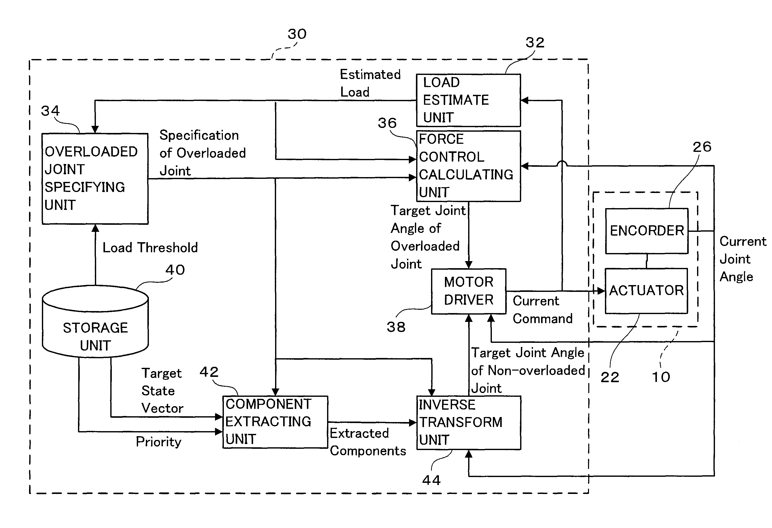
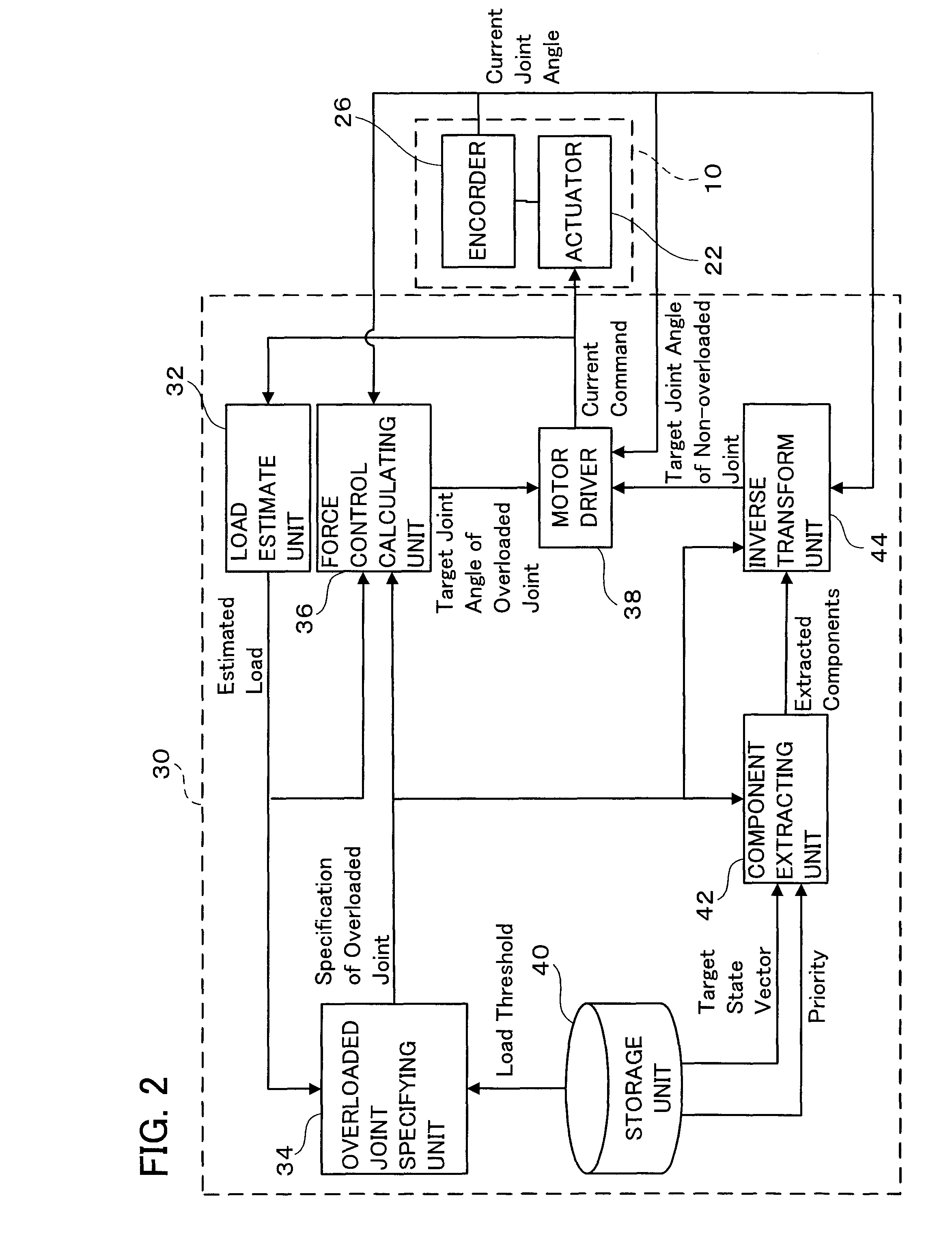
[0088]The second embodiment will be described hereinafter. FIG. 4 shows the block diagram of a multi-joint robot relating to the second embodiment. FIG. 4 applies the same reference numerals to the same components as those in the block diagram in the first embodiment illustrated in FIG. 2. The descriptions of the components with the same reference numerals applied to FIG. 2 will be omitted.

[0089]The robot mechanism 10b of the multi joint robot relating to the second embodiment has a force sensor 28 on the end link (the seventh link 12g in FIG. 1). The components other than the force sensor 28 are the same as those of the robot mechanism 10 in the first embodiment, and the descriptions thereof will be omitted. The force sensor 28 is installed between the end effector 14 (refer to FIG. 1) and the end link of the robot mechanism 10b. The force sensor 28 detects the external force acting on the robot mechanism 10b through the end effector 14.

[0090]The controller 30b in the second embodi...

third embodiment

[0093]Now the third embodiment will be described. The first embodiment and the second embodiment have used the inverse transform formula for determining the target joint angle of the non-overloaded joint. In the third embodiment, the target value (target drive quantity) for controlling each joint is the joint angular velocity, and the target state vector is expressed by the target velocity of the end link (velocity in the direction of each of the x, y, and z axes in the coordinate system in FIG. 1, roll angular velocity, pitch angular velocity, and yaw angular velocity). When an overloaded joint does not exist, the multi-joint robot in the third embodiment is controlled by the so-called resolved motion rate control. This embodiment applies the resolved motion rate control to determining the target value (angular velocity) of the non-overloaded joint. This embodiment refers to FIG. 2 as to the block diagram of the multi-joint robot. However, the inverse transform unit 44 in FIG. 2 is...


PUM


Abstract

The present invention provides a multi-joint robot that, when the loads acting on some of joints are overloaded, controls the joints so as to continue the work as far as possible while easing the overloaded state. The load estimate unit (32) estimates the load acting on each joint, and the overloaded joint specifying unit (34) specifies an overloaded joint of which the estimated load is greater than a threshold. The storage unit (40) stores a target state vector of an end link of the robot and stores a predetermined priority with respect to the components of the vector. The component extracting unit (42) extracts the same number of components as that of non-overloaded joints from the target state vector in order of a higher priority. The force control calculating unit (36) determines the target drive quantity for driving the overloaded joint in the same direction as that of the load. The inverse transformation unit determines the target drive quantities with respect to the non-overloaded joints so as to realize the extracted components. Thus, the non-overloaded joints can be controlled so as to follow the target state vector as far as possible, while the overloaded joints are controlled in a direction to reduce the load.

Description

CROSS REFERENCE TO RELATED APPLICATION[0001]The present application claims priority to Japanese Patent Application No. 2006-175063, filed on Jun. 26, 2006, the contents of which are hereby incorporated into this specification by reference.FIELD OF THE INVENTION[0002]The present invention relates to a multi joint robot and a control program for the multi-joint robot (computer program product for controlling the multi-joint robot).BACKGROUND ART[0003]The multi-joint robot has a multi-joint robot mechanism and a controller for controlling the mechanism. In this specification, a “multi joint robot mechanism” may be referred to as a “multi joint robot” or simply “robot”. The multi joint robot mechanism in this specification refers to a robot that comprises plural links and plural joints, wherein adjoining links are connected by a joint and at least two or more joints are disposed between a base link and an end link. The end link herein referred to is not necessarily limited to a link tha...

Claims


Application Information

Patent Timeline
Patent Type & Authority Applications(United States)
IPC IPC(8): B25J9/10B25J17/00B25J13/08
CPCB25J9/1628G05B2219/40461G05B2219/37342
Inventor NAKAJIMA, YUICHIRO
Owner TOYOTA JIDOSHA KK
Why Eureka
Try Eureka