Heat absorbing and reflecting shield for air breathing heat engine

a technology of air breathing and heat engine, which is applied in the direction of machine/engine, combination engine, reciprocating combination engine, etc., can solve the problems of additional temperature rise, reduce the efficiencies of air compression (gas), and increase the flow of air, so as to improve the overall thermal efficiencies of the ct

Inactive Publication Date: 2010-09-23
LONGARDNER ROBERT L
View PDF19 Cites 26 Cited by
  • Summary
  • Abstract
  • Description
  • Claims
  • Application Information

AI Technical Summary

Benefits of technology

[0015]The present invention provides for the means to absorb the radiated and convected heat from compression aspects into a ducted stream of conditioned air. Further, the invention provides for the means to r

Problems solved by technology

This mechanical work causes a temperature rise in the flow of air.
Also when the radiation from the combustor aspects is reflected into the compressor aspects, it causes an additional temperature rise, all of which reduces the efficiencies of the compression of air (gas).
This combustion gas diffused and expanded into the turbine at a rate depending temperature drop, and when the radiated heat from the combustor is reflected into the turbine aspects, this reheat from combustor radiation hinders the drop in temperature along with slowing down the rate of gas expansion which essentially reduces the power thereby reducing the thermal efficiencies.
This radiated heat, as an example, will cause a loss of thermal efficiency on a 90° F. day on average of a calculated 5%+, likewise the radiated heat reflected into the turbine could result in a loss in efficiency calculated at 4%+.
A problem with the heat produced and convected in existing acoustic enclosures is the tendency to retain that heat being produced by the CT c

Method used


Image

  • Heat absorbing and reflecting shield for air breathing heat engine
  • Heat absorbing and reflecting shield for air breathing heat engine
  • Heat absorbing and reflecting shield for air breathing heat engine

Examples


Embodiment Construction

[0026]For the purposes of promoting an understanding of the principles of the invention, reference will now be made to the embodiments illustrated in the drawings and specific language will be used to describe the same. It will nevertheless be understood that no limitation of the scope of the invention is thereby intended.

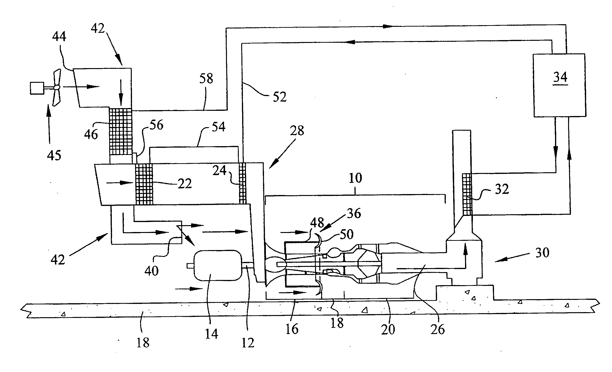
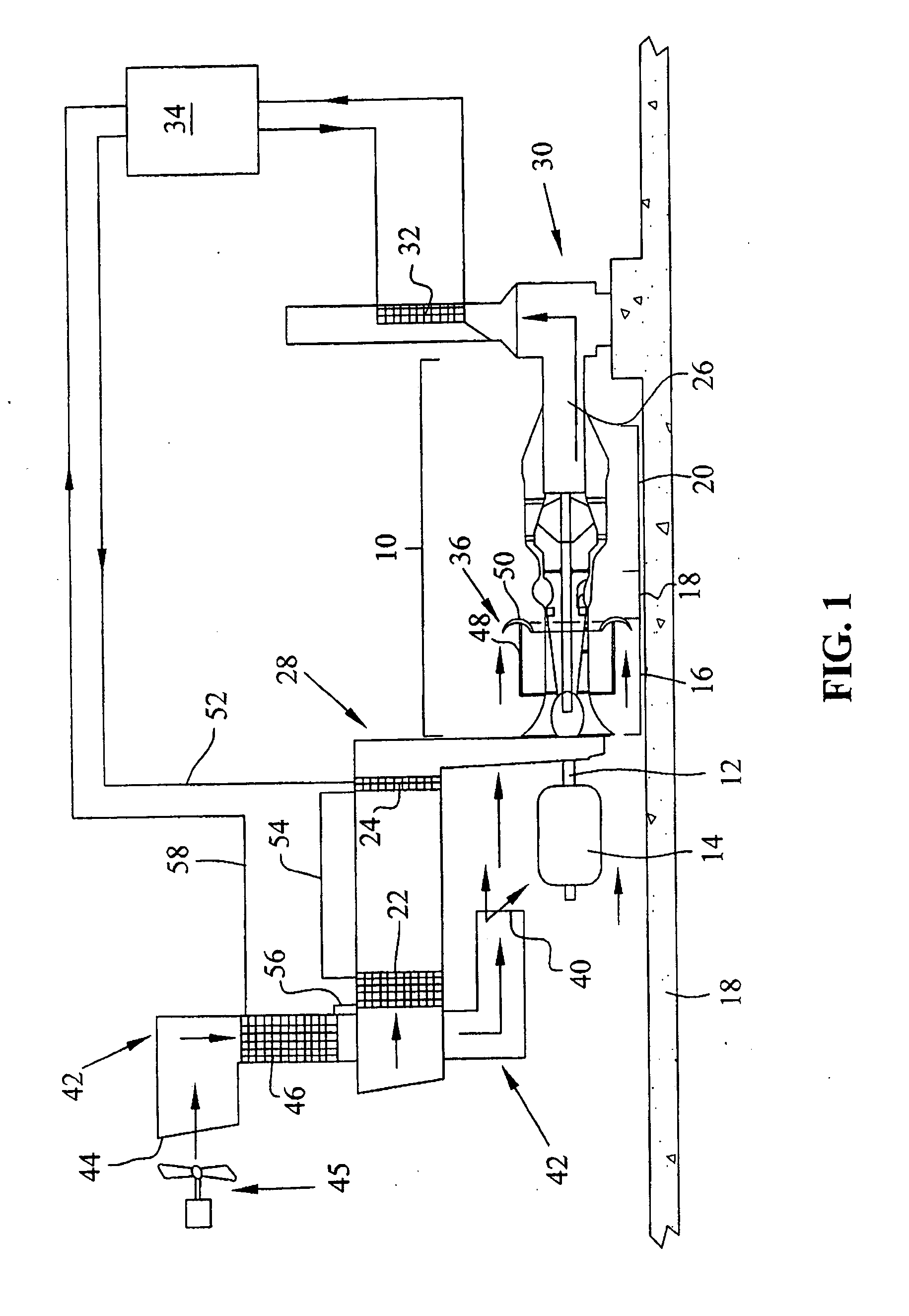
[0027]Referring now to FIG. 1, a combustion turbine, or air breathing heat engine, is schematically shown at 10, and as is conventional with such gas turbines, includes compressor 16, combustion portion 18, and turbine 20. Turbine 20 utilizes the gases from combustion portion 18 to drive shaft 12, which is drivingly connected to generator 14 for power generation. Turbine 10 operates in the stationary mode in that, unlike the aero-related turbines on which its design is based and which are naturally moved while used in flight, the turbine is fixedly mounted to a support surface or on the ground during use.

[0028]Intake air duct 28 supplies air to compressor 16 of tur...


PUM


Abstract

A system for adjusting ambient air temperature shielding an engine. The system includes an engine having first and second ends and a heat generating source, and a shield having a substantially cylindrical portion defining an interior cavity. At least a portion of the heat generating source is disposed in the cavity. The shield has a heat reflecting interior surface facing the cavity and an opposing exterior surface. The interior surface reflects heat generated by the heat source.

Description

BACKGROUND OF THE INVENTION[0001]1. Field of the Invention[0002]The present invention pertains to air breathing heat engines such as combustion turbines (CT) comprised of a compressor, combustor, and turbine, and, in particular, to a system for cooling such heat engines.[0003]2. Description of Related Art[0004]The aero-derivative and framed CTs are rapidly becoming the power generators of choice for electrical power and for direct drive. Earlier applications of CTs were configured to meet spikes in energy dispatch and to meet those spikes with very little regard for heat rates. Due to many favorable features of CTs such as being relatively environmental friendly, as well as improvement in heat rates and reduced capital costs, CTs are increasingly being employed in intermediate and base load generation and now likely will be the wave of the foreseeable future.[0005]It is obvious that when the compressor aspects of a CT are cooled, the work compressing the air mass is reduced. For the...

Claims


Application Information

Patent Timeline
IPC IPC(8): F02B73/00
CPCF05D2250/231F02C7/24
Inventor LONGARDNER, ROBERT L.
Owner LONGARDNER ROBERT L
Why Eureka
Try Eureka