
Method and apparatus for improving dehumidification

a technology of dehumidification and control logic, applied in the field of air conditioning systems, can solve the problems of complex control logic, high cost, and complicated techniques, and achieve the effect of increasing cooling capacity

Inactive Publication Date: 2010-09-23
CARRIER CORP
View PDF17 Cites 9 Cited by
  • Summary
  • Abstract
  • Description
  • Claims
  • Application Information

AI Technical Summary

Benefits of technology

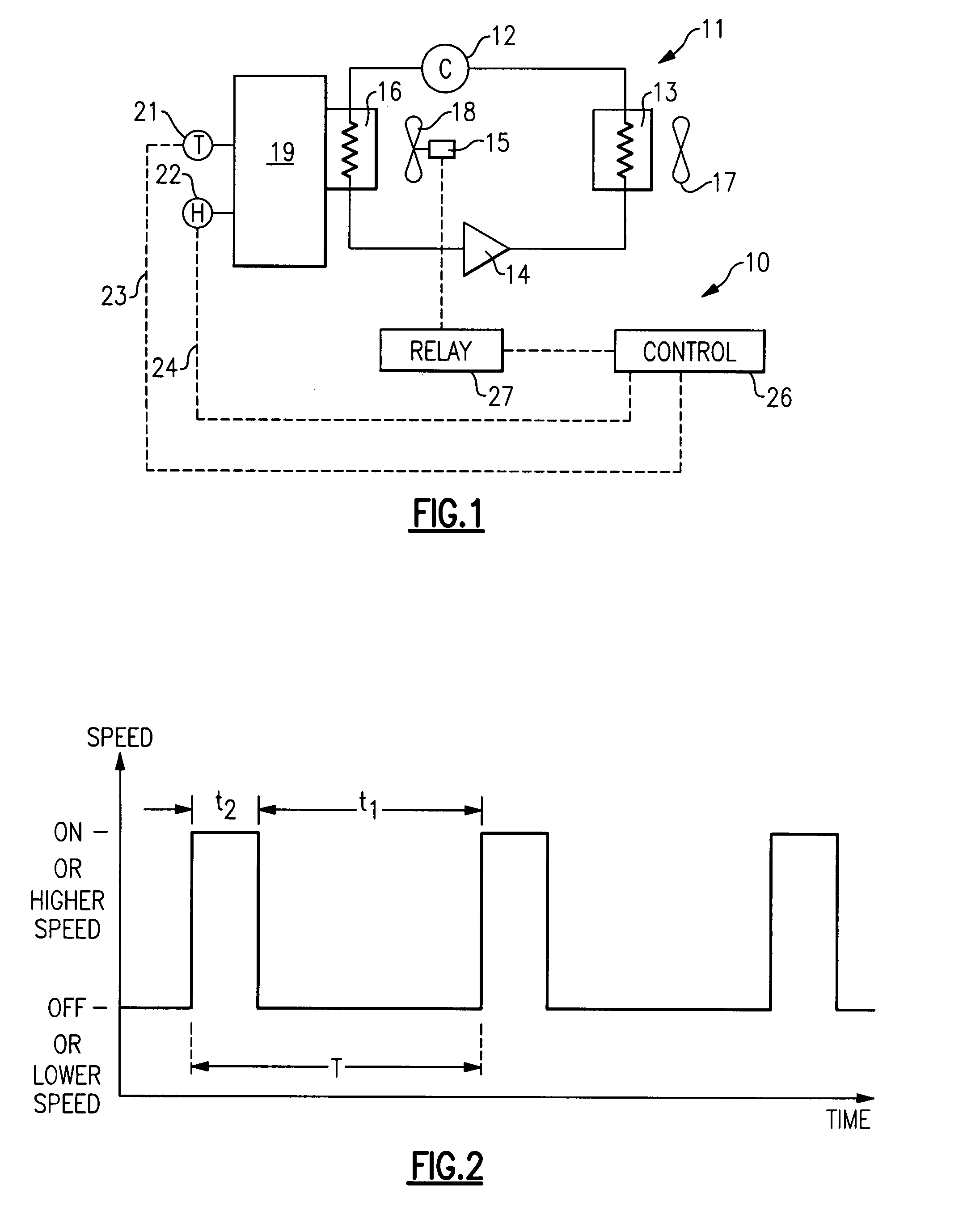
[0006]Briefly, in accordance with one aspect of the invention, the respective levels of temperature and humidity in a conditioned space are controlled by selectively operating an evaporator fan by periodically switching between the first speed and the second speed, with the second speed being higher than the first speed. Furthermore, when higher cooling capacities are desired, the period of time associated with the indoor fan operation at the second speed is increased, and when lower relative humidity levels are desired, the period of time associated with the indoor fan operation in the first speed is increased.

Problems solved by technology

However, such techniques are quite often very complicated, involve additional expensive components and require complex control logic.

Method used


Image

  • Method and apparatus for improving dehumidification
  • Method and apparatus for improving dehumidification

Examples


Embodiment Construction

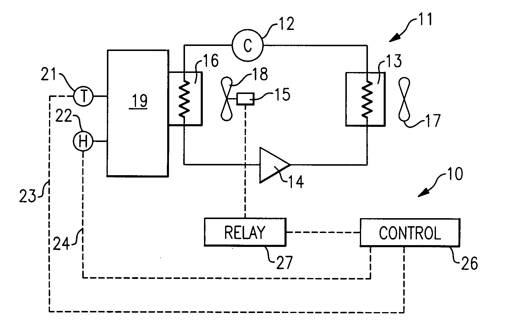
[0012]The invention is shown generally at 10 as incorporated into an air conditioning system 11 which includes, in serial flow relationship, a compressor 12, a heat rejection heat exchanger 13, an expansion device 14 and a heat accepting heat exchanger 16. The heat rejection heat exchanger assembly includes a motor driven air-moving device or fan 17 and the heat accepting heat exchanger assembly includes an air-moving device or fan 18 driven by an electric motor 15. As known, the heat rejection heat exchanger 13 is a condenser for subcritical applications and a gas cooler for transcritical applications, while a heat accepting heat exchanger 16 is generally known as an evaporator. In operation, the basic conventional air conditioning system 11 is typically utilized to provide cooling to a conditioned space 19. While the indoor airflow driven by the indoor fan 18 passes over external surfaces of the evaporator 16 and is delivered to the conditioned space 19, it is cooled and typically...


PUM


Abstract

Comfort temperature and humidity levels in a conditioned space are controlled by cycling the speed of an evaporator fan motor in such a manner that, during time periods when higher sensible capacity is desired, the time in which the fan motor operates at a higher speed is increased, and during time periods when a higher latent capacity is desired, the time in which the fan motor operates at a lower speed is increased. The fan motor may be a single speed motor that is switched between on and off positions, or it may be a multiple speed motor that is cycled between a higher speed and a lower speed.

Description

FIELD OF THE INVENTION[0001]This invention relates generally to air conditioning systems and, more particularly, to control of an indoor fan to obtain improved dehumidification.BACKGROUND OF THE INVENTION[0002]In air conditioning systems, it is known that the gross cooling capacity of the refrigerant system, or the overall cooling capacity of an evaporator, is increased with indoor fan speed. This higher capacity is the result of higher indoor airflow moving over the evaporator external surfaces and therefore improving overall evaporator heat transfer coefficient.[0003]It is also known that, when an evaporator fan is operating at a lower speed, with less air being passed over the evaporator, evaporator operates at a lower sensible heat ratio. In other words, the latent capacity component in the overall evaporator capacity is increased while the sensible capacity component is reduced, such that more moisture will be removed from each unit of the air on a relative basis and the overal...

Claims


Application Information

Patent Timeline
Patent Type & Authority Applications(United States)
IPC IPC(8): F25D17/06F25D17/04F24F3/14
CPCF24F3/1405F24F11/0012Y02B30/746F24F11/0079F24F2003/1446F24F11/0015F24F11/30F24F2110/10F24F2110/20F24F11/77Y02B30/70F24F11/81F24F11/88
Inventor LIFSON, ALEXANDERTARAS, MICHAEL F.
Owner CARRIER CORP
Learn More