System and method for ultra-high frequency ultrasound treatment

a high-frequency ultrasound and ultra-high-frequency technology, applied in ultrasonic/sonic/infrasonic diagnostics, ultrasonic/sonic/infrasonic diagnostics, diagnostic recording/measure, etc., can solve the problems of limiting the use of low-frequency applications, unable to treat with low-frequency transducers, and unable to achieve maximum efficiency and/or maximum acoustic output, and facilitate control of operation frequency , the effect o

Active Publication Date: 2010-09-23
GUIDED THERAPY SYSTEMS LLC
View PDF103 Cites 116 Cited by
  • Summary
  • Abstract
  • Description
  • Claims
  • Application Information

AI Technical Summary

Benefits of technology

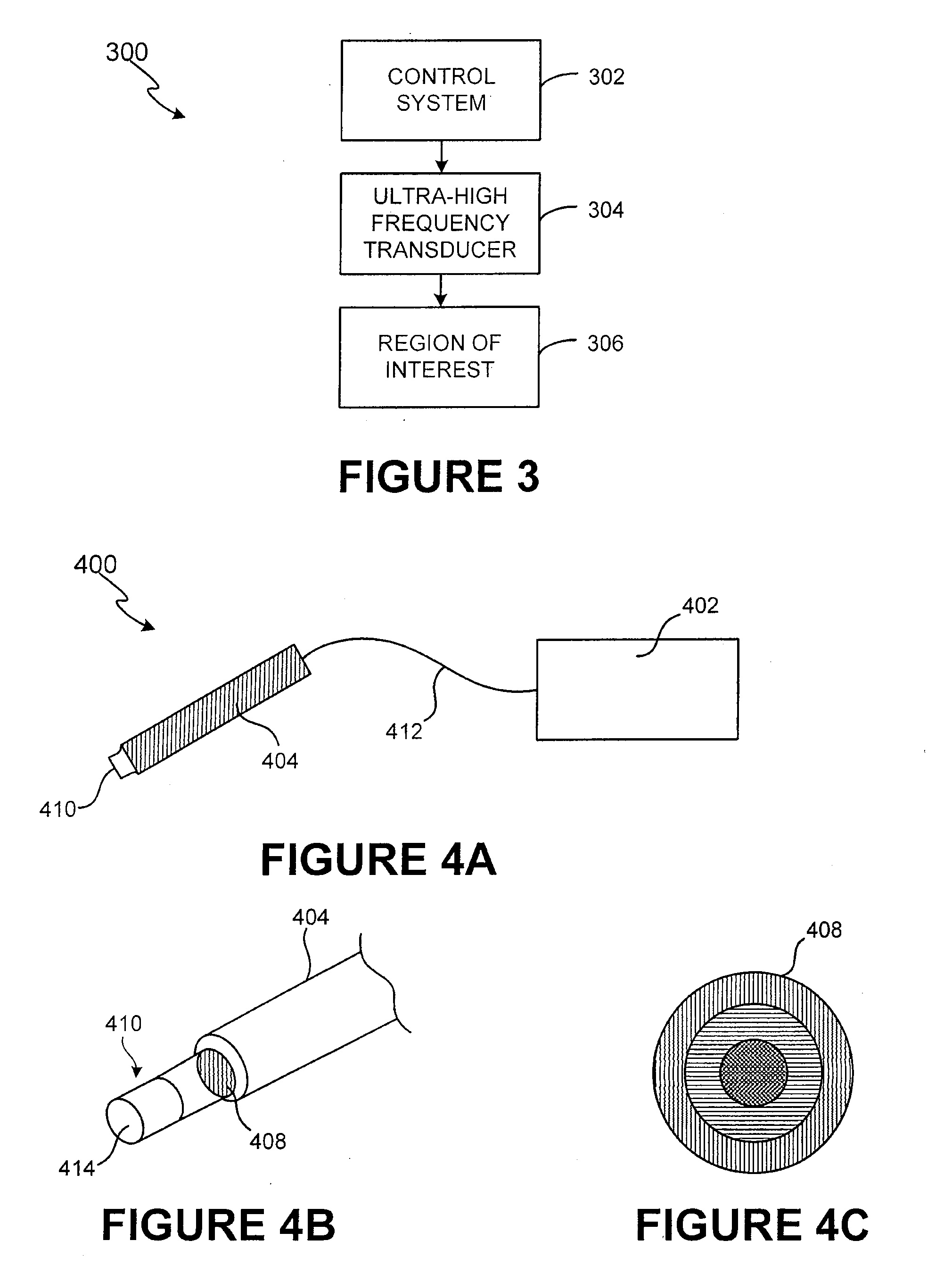
[0007]An exemplary ultra-high frequency ultrasound transducer system comprises a control system and a transducer configured to provide treatment to the superficial and / or internal superficial regions of interest. The ultra-high frequency ultrasound transducer may be configured to operate at higher frequencies and controlled power levels to provide safe, controlled treatment to superficial, and / or internal superficial tissue, e.g. an organ or tissue surface regions of interest. For example, higher frequencies within the range from approximately 20 MHz to 500 MHz or more may be utilized. In addition, by operating at optimum efficiency, the acoustic intensity can be suitably configured at high levels with the use of controlled, moderate power output levels. In accordance with an exemplary embodiment of the present invention, the ultra-high frequency ultrasound transducer can comprise a transduction element having a piezoelectrically active layer, matching layers and / or other materials for generating radiation or acoustical energy. The transduction element can comprise single or multiple elements.
[0008]In accordance with an exemplary embodiment of the present invention, the transduction element may be configured with an application device to facilitate coupling of the acoustical energy to the superficial and / or internal superficial regions of interest. The application device may be configured in various manners for coupling to the patient to provide treatment to the superficial and / or internal superficial regions of interest. In accordance with another exemplary embodiment, the transduction element may be configured on a minimally-invasive application device, such as a needle or other medical instrument, to permit the transduction element to come into substantially direct contact with various facia, e.g., the SMAS tissue layers, to facilitate treatment. Thus, instead of being placed on the outer surface of the skin, the application device may be inserted into the patient to come into more proximate acoustical contact with the targeted region for treatment.
[0009]In accordance with an exemplary embodiment of the present invention, an exemplary control system comprises a drive circuit and a feedback network configured to control the operation of the ultra-high frequency ultrasound transducer. The drive circuit is configured to control power to the transduction element and can comprise various configurations, with and without voltage oscillation. In accordance with an exemplary embodiment, the drive circuit is configured to drive the frequency of the transduction element at the resonant frequency to facilitate maximum efficiency and / or maximum acoustic output. The feedback element is configured to use electrical signals from the driver circuit and / or the transduction element to facilitate control of the frequency of operation to provide optimum electro-acoustic conversion of energy. In addition, the control system can be suitably coupled to the transduction element in various manners.

Problems solved by technology

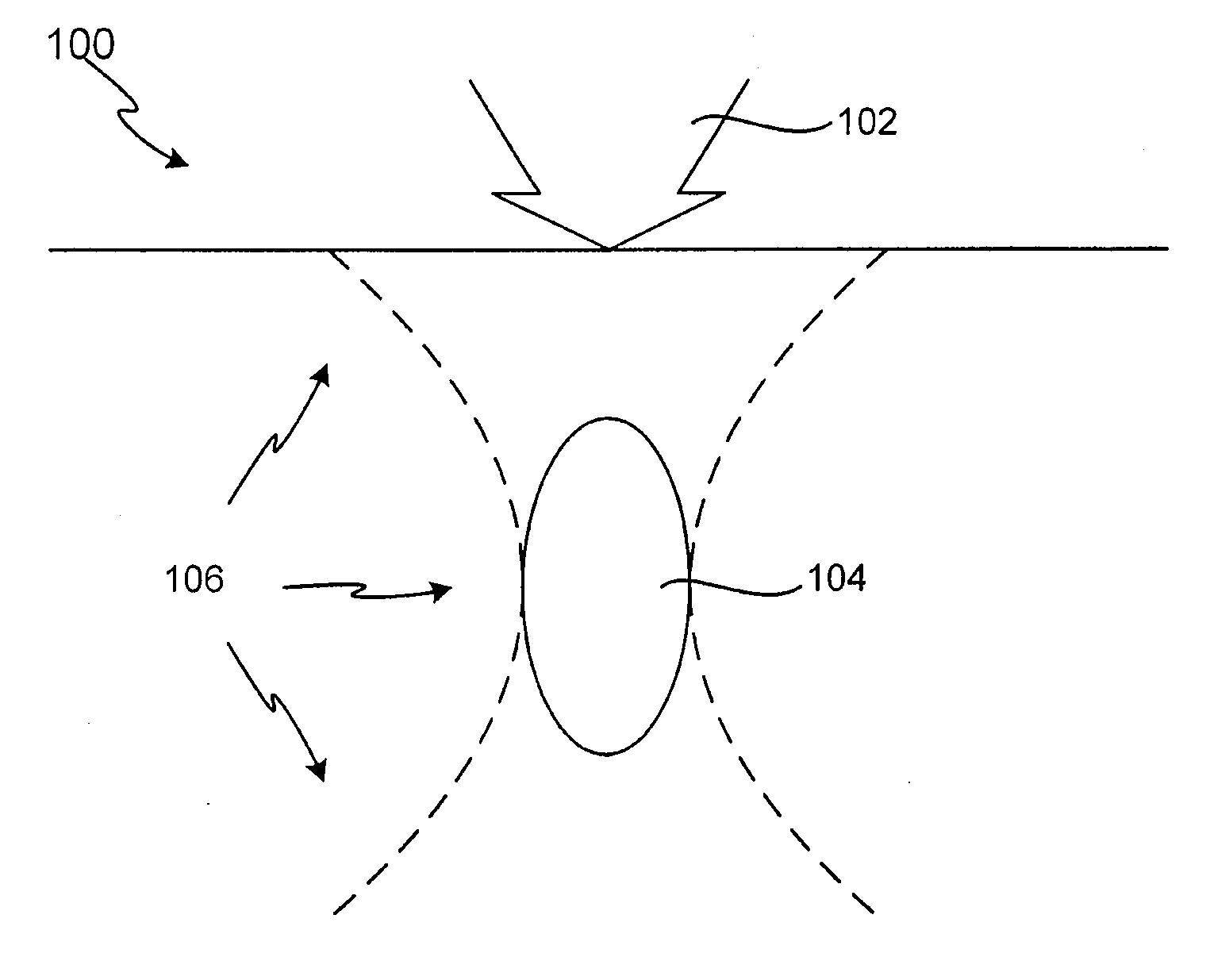
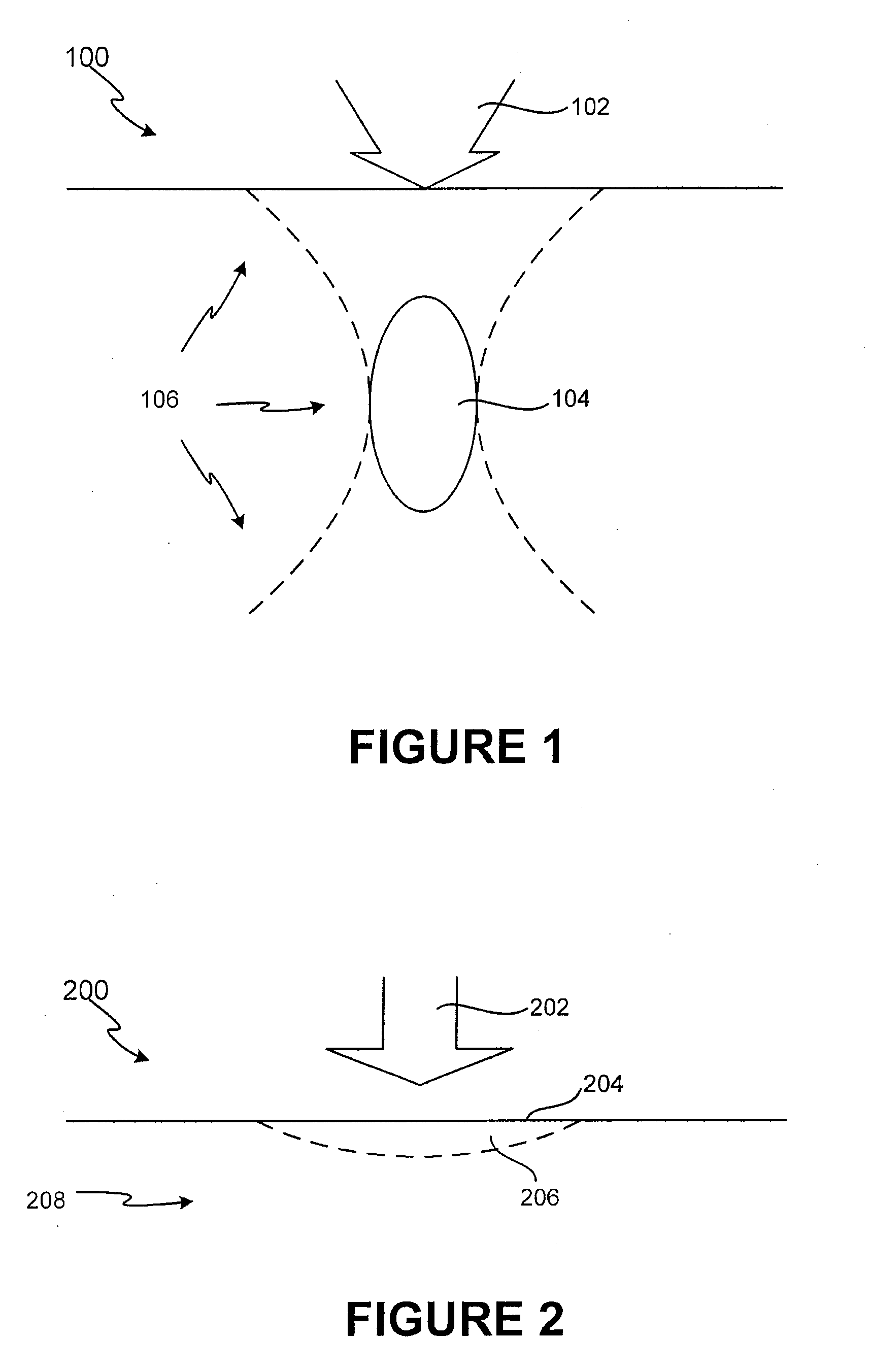
Unfortunately, currently available low frequency transducers cannot be used to treat the superficial regions, thus limiting the use of low-frequency application 100.
Another undesirable side effect of low-frequency therapy is that the acoustic energy must pass through intervening tissue layers before reaching the desired deep treatment area.
This causes the focal spot size to widen, making it difficult to control the location of the focal spot, and making dosimetry also difficult to optimize.

Method used


Image

  • System and method for ultra-high frequency ultrasound treatment
  • System and method for ultra-high frequency ultrasound treatment
  • System and method for ultra-high frequency ultrasound treatment

Examples


Embodiment Construction

[0018]The present invention may be described herein in terms of various components and processing steps. It should be appreciated that such components and steps may be realized by any number of hardware devices and components configured to perform the specified functions. For example, the present invention may employ various medical treatment devices, visual imaging and display devices, input terminals and the like, which may carry out a variety of functions under the control of one or more control systems or other control devices. In addition, the present invention may be practiced in any number of medical or treatment contexts and that the exemplary embodiments relating to ultra-high frequency ultrasound treatment as described herein are merely a few of the exemplary applications for the invention. For example, the principles, features and methods discussed may be applied to any medical or other tissue or treatment application.

[0019]In accordance with various aspects of the presen...


PUM


Abstract

A non-invasive ultra-high frequency ultrasound treatment method and system are provided. An exemplary method and system comprise a high-frequency ultrasound transducer system configured for providing ultrasound treatment to a patient such that the superficial and / or subcutaneous regions of the patient can be treated. An exemplary high-frequency ultrasound transducer system comprises a control system and a transducer configured to provide treatment to the superficial and / or subcutaneous regions of interest. The high-frequency ultrasound transducer may be configured to operate at higher frequencies and controlled power levels to provide treatment to the superficial and / or subcutaneous regions of interest. For example, higher frequencies within the range from approximately 20 MHz to 500 MHz or more may be utilized.

Description

CROSS-REFERENCE TO RELATED APPLICATIONS[0001]This application is a continuation of U.S. application Ser. No. 11 / 245,999 entitled “SYSTEM AND METHOD FOR ULTRA-HIGH FREQUENCY ULTRASOUND TREATMENT” which was filed on Oct. 6, 2005, now U.S. Pat. No. ______, which in turn claims priority to and benefit of U.S. Provisional Application No. 60 / 616,356, entitled “System and Method for Ultra-High Frequency”, and filed on Oct. 6, 2004, all of which are incorporated herein by reference.FIELD OF INVENTION[0002]This invention generally relates to an ultrasound system, and more particularly, to a method and system for ultra-high frequency ultrasound treatment.BACKGROUND OF THE INVENTION[0003]Many conventional applications of therapeutic ultrasound have employed low frequency transducers. These transducers have operational frequencies that typically range from 500 kHz to 1.5 MHz. Such low frequency transducers are often preferred because they allow for acoustical energy to be focused very deep into...

Claims


Application Information

Patent Timeline
Patent Type & Authority Applications(United States)
IPC IPC(8): A61N7/00
CPCA61H23/0245A61B17/320068A61B8/00A61N7/02A61B2017/320069A61N2007/0034A61N2007/0052
Inventor BARTHE, PETER G.SLAYTON, MICHAEL H.
Owner GUIDED THERAPY SYSTEMS LLC
Why Eureka
Try Eureka