Joint cover assembly and kit comprising this joint cover assembly as well as installation method thereof

a joint cover and assembly technology, applied in the direction of roof coverings, structural elements, building components, etc., can solve the problems of difficulty in covering the gap that may be formed, problems encountered with conventional edge moldings, etc., and achieve the effect of reducing warping or deterioration of the material surfa

Inactive Publication Date: 2010-09-30
PERGO
View PDF127 Cites 10 Cited by
  • Summary
  • Abstract
  • Description
  • Claims
  • Application Information

AI Technical Summary

Benefits of technology

[0049]The adhesive may be attached to any location where two pieces of the assembly are joined. Preferably, adhesive is only applied to one of the arms of the first molding element in order to allow or accommodate some slight relative movement that may occur during changes of temperature, for example. This relative movement is known in the flooring art as “float”. Allowing float may also eliminate unneeded material stresses as well, thereby reducing warping or deterioration of the material surface.

Problems solved by technology

A problem is encountered, however, when flooring materials that are dissimilar in shape or texture ere used.
For example, when a hard floor is placed adjacent a carpet, problems are encountered with conventional edge moldings placed therebetween.
Such problems include difficulty in covering the gap that may be formed between the floorings having different height, thickness or texture.

Method used


Image

  • Joint cover assembly and kit comprising this joint cover assembly as well as installation method thereof
  • Joint cover assembly and kit comprising this joint cover assembly as well as installation method thereof
  • Joint cover assembly and kit comprising this joint cover assembly as well as installation method thereof

Examples


Embodiment Construction

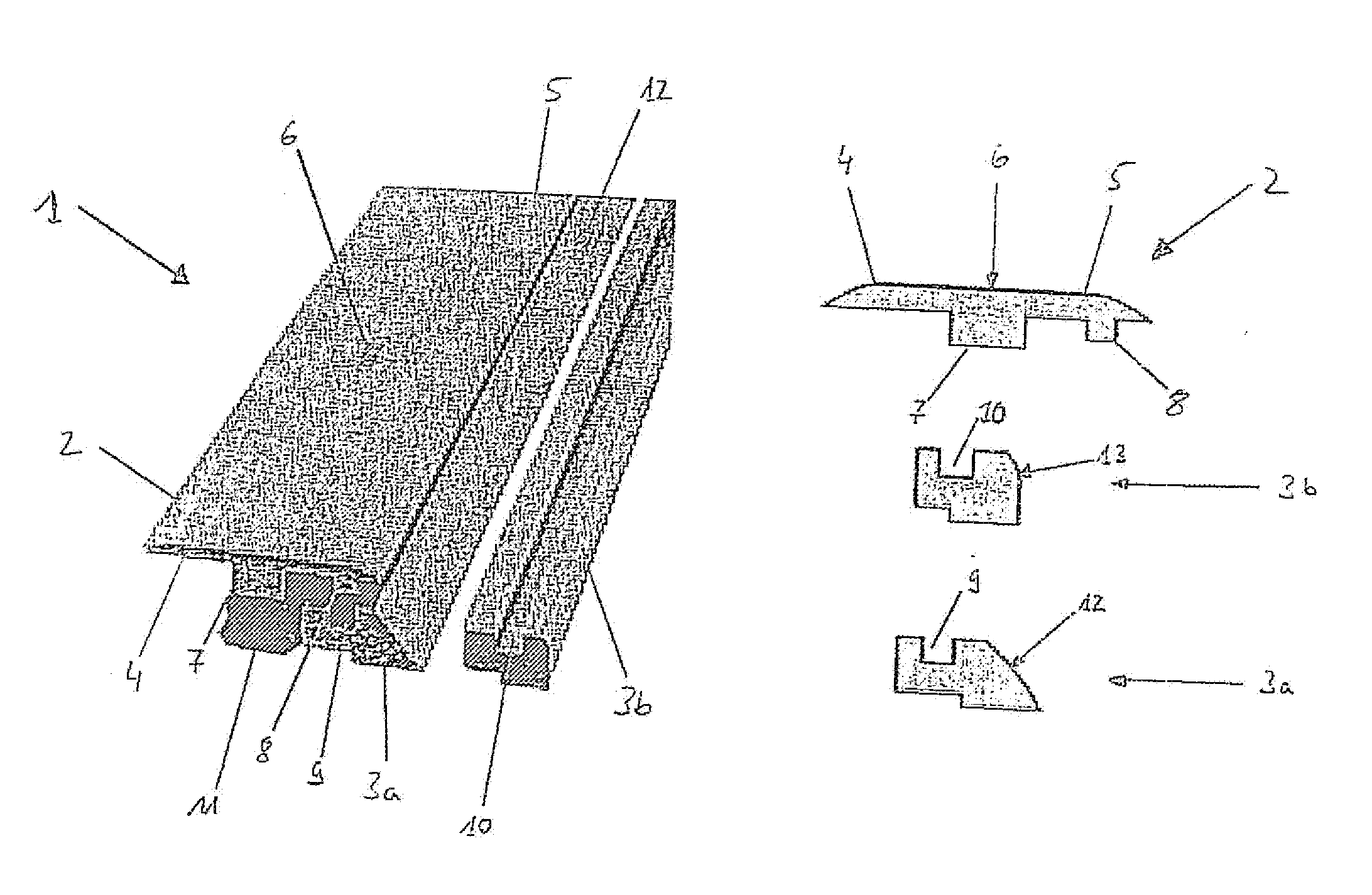
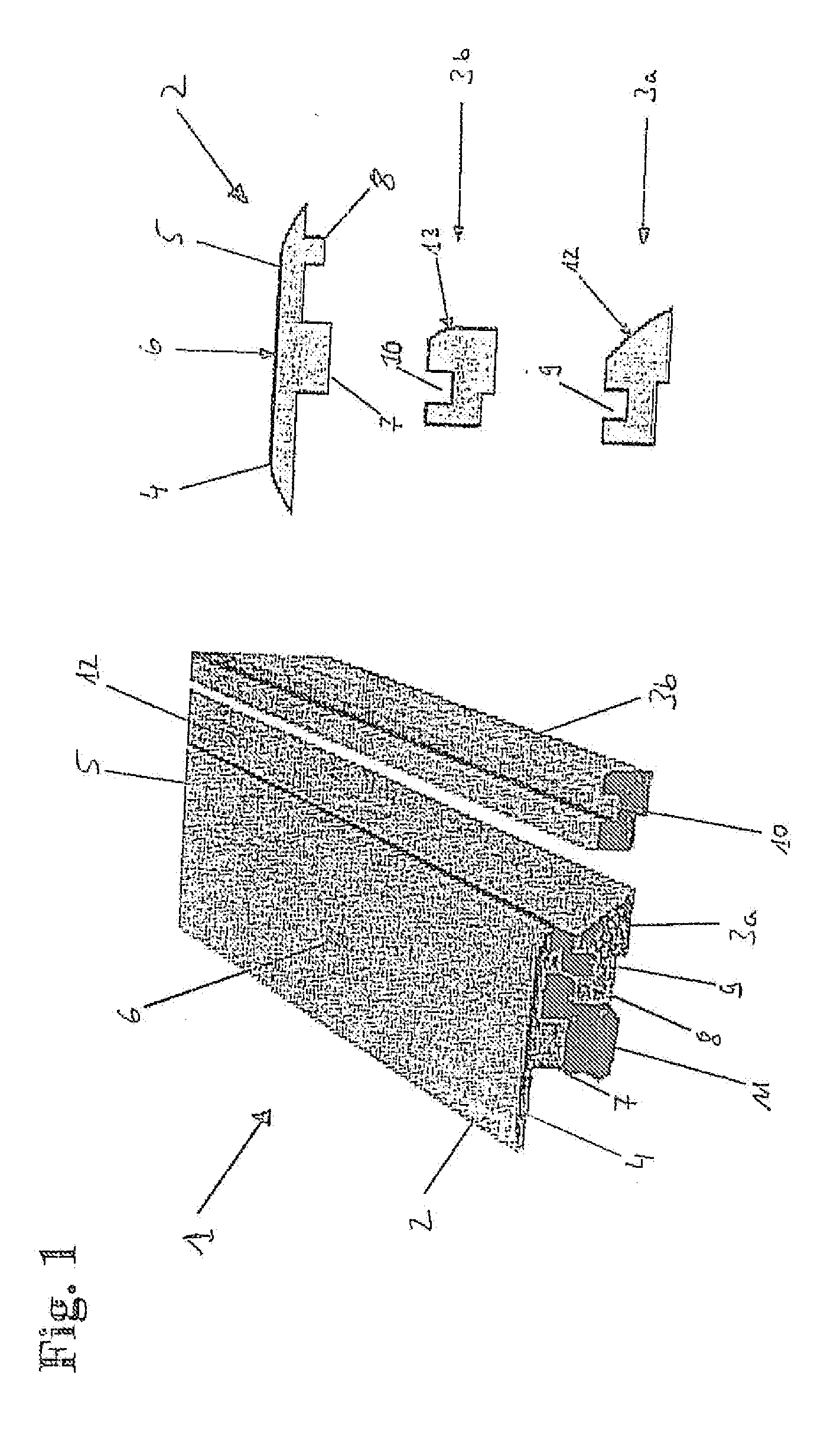
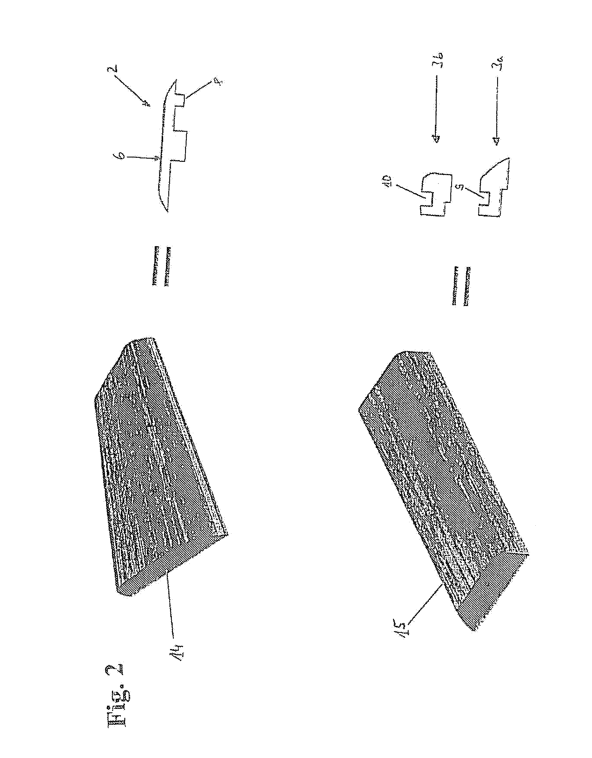
[0058]In FIG. 1, a joint cover assembly 1 according to U.S. Pat. No. 6,860,047 and comprises a first, T-shaped molding element 2 as well as two different second molding elements 3a,3b, the first of which 3a is illustrated in a near joint position with respect to the first molding element 2. The first molding element 2 has two arms 4,5 being substantially in one plane and supporting the first molding element's exposed surface 6. Perpendicular to the first and second arm 4,5, the first molding element 2 comprises a foot 7 being disposed underneath the exposed surface 6. On the bottom side of the arm 5, a tongue 8 is disposed, which is to cooperate with a corresponding groove 9 disposed within the second molding element 3a, or the groove 10 being disposed in the second molding element 3b. The foot 7 is to be inserted into a track 11 for fixation of the entire joint cover assembly to a sub surface (not shown). The first molding element 2 is disposed adjacent to a second molding element ...


PUM


Abstract

The invention relates to a joint cover assembly for covering a gap between two floor elements covering a subsurface, the assembly comprising a first molding element comprising an upper section having an exposed surface, the exposed surface comprising a décor, and a foot depending therefrom, wherein the foot has a gripping groove extending towards the exposed surface and being defined by two side walls; and a second molding element comprising an upper surface and a lower surface, to be joined to the first molding element, as well as an exposed surface comprising a décor, wherein the lower surface has a groove extending towards the upper surface and being defined by two side walls; characterised in that the joint cover assembly furthermore comprises a track having two upstanding sections, wherein the distance between the upstanding sections corresponds substantially to the width of the foot and also to the distance between a gripping groove's side wall and a proximal side wall of the second molding element's groove. Furthermore, the invention relates to a kit comprising such joint cover assembly. Finally, the invention relates to a method of covering a sub floor adjacent a floor element by using this joint cover assembly or this kit.

Description

1. FIELD OF THE INVENTION[0001]The invention is a joint cover assembly that includes a molding, similar to a transition molding between two separate parts, such as a T-Molding, for covering a gap that may be formed between adjacent panels in a generally planar surface, such as between two adjacent flooring or wall or ceiling materials; or between a floor and a hard surface or carpet, or even a riser and a runner in a step (or a series of steps).2. BACKGROUND OF THE INVENTION[0002]Hard surface floors, such as wood (solid or engineered) or laminate flooring have become increasingly popular. As such, many different types of this flooring are assembled by providing a plurality of similar panels. The differing types of panels that have developed, of course, may have differing depths and thicknesses. The same is true when a laminate floor (often referred to as “floating floor”) abuts another hard surface, such as a resilient surface (such as vinyl), tile or another laminate surface, a cer...

Claims


Application Information

Patent Timeline
Patent Type & Authority Applications(United States)
IPC IPC(8): E04F19/02E04B1/62E04B1/00
CPCE04F19/062E04F2019/0454E04F19/065E04F19/063
Inventor KORNFALT, SVEN
Owner PERGO
Why Eureka
Try Eureka