Systems, Methods, and Apparatus for Modifying Power Output and Efficiency of a Combined Cycle Power Plant

power output technology, applied in the field of combined cycle power plants, can solve the problems of compressor surge, compressor surge, reduced power output and efficiency of gas turbines, etc., and achieve the effects of modifying the power output and efficiency of a combined cycle power plant system, and maintaining the performance of the gas turbin

Inactive Publication Date: 2010-09-30
GENERAL ELECTRIC CO
View PDF9 Cites 9 Cited by
  • Summary
  • Abstract
  • Description
  • Claims
  • Application Information

AI Technical Summary

Benefits of technology

[0008]Embodiments of the invention can address some or all of the needs described above. Certain embodiments of the invention are directed generally to systems, methods, and apparatus for modifying the power output and efficiency of a combined cycle power plant. According to one embodiment, a method for modifying the power output and efficiency of a combined cycle power plant can be provided, wherein the combined cycle power plant includes a compressor for a gas turbine, a combustor, and a heat recovery steam generator (“HRSG”). The method can include extracting excess air from the compressor and expanding the excess air to generate power. The method can also include mixing the expanded air with a combustible fuel to generate a heated combustion product. The method can further include mixing the heated combustion product with exhaust from the gas turbine so that the temperature and mass flow of the exhaust is increased prior to being introduced to the HRSG.
[0009]According to another embodiment of the invention, a system for modifying the power output and efficiency of a combined cycle power plant system can be provided. The system can include a compressor of a gas turbine, wherein the compressor is operable to generate compressed air and is further operable to extract excess compressed air to maintain performance of the gas turbine. The system can also include a combustor operable to mix at least a portion of the compressed air with a combustible fuel to generate a heated combustion product and to operate a gas turbine to produce power. The system can also include an air expander operable to receive the excess compressed air from the compressor and to expand it to produce power. Furthermore, the system can include a fired heater operable to receive the expanded excess air from the air expander and to mix the expanded air with the combustible fuel to generate a heated combustion product. Finally, the system can include a HRSG operable to receive the heated combustion product from the fired heater and the exhaust from the gas turbine for power production.

Problems solved by technology

In some gas turbine applications, the gas turbine pressure ratio exceeds the operational pressure limits of the compressor, resulting in compressor surge.
This compressor surge can occur when low BTU (British Thermal Unit) fuels are used.
When compressor surge occurs, it reduces the power output and efficiency of the gas turbine and can also cause a catastrophic failure in the system.
While this approach eliminates compressor surge, mixing the cold ambient air with the hot discharge air results in reduced air density and mass flow to the gas turbine.
Consequently, gas turbine performance declines, and the amount of available gas turbine exhaust dwindles.
Thus, when the two gases are mixed, the air temperature at the inlet of the HRSG is reduced, and with less heat provided to its inlet, the HRSG is unable to produce the same amount of steam.
Moreover, because the discharge air contains energy in the form of pressure energy, this energy is wasted when fed directly to the inlet of the HRSG.

Method used


Image

  • Systems, Methods, and Apparatus for Modifying Power Output and Efficiency of a Combined Cycle Power Plant
  • Systems, Methods, and Apparatus for Modifying Power Output and Efficiency of a Combined Cycle Power Plant
  • Systems, Methods, and Apparatus for Modifying Power Output and Efficiency of a Combined Cycle Power Plant

Examples


Embodiment Construction

[0016]The invention now will be described more fully hereinafter with reference to the accompanying drawings, in which example embodiments of the invention are shown. This invention may, however, be embodied in many different forms and should not be construed as limited to the example embodiments set forth herein; rather, these embodiments are provided so that this disclosure will convey the scope of the invention to those skilled in the art. Like numbers refer to like elements throughout.

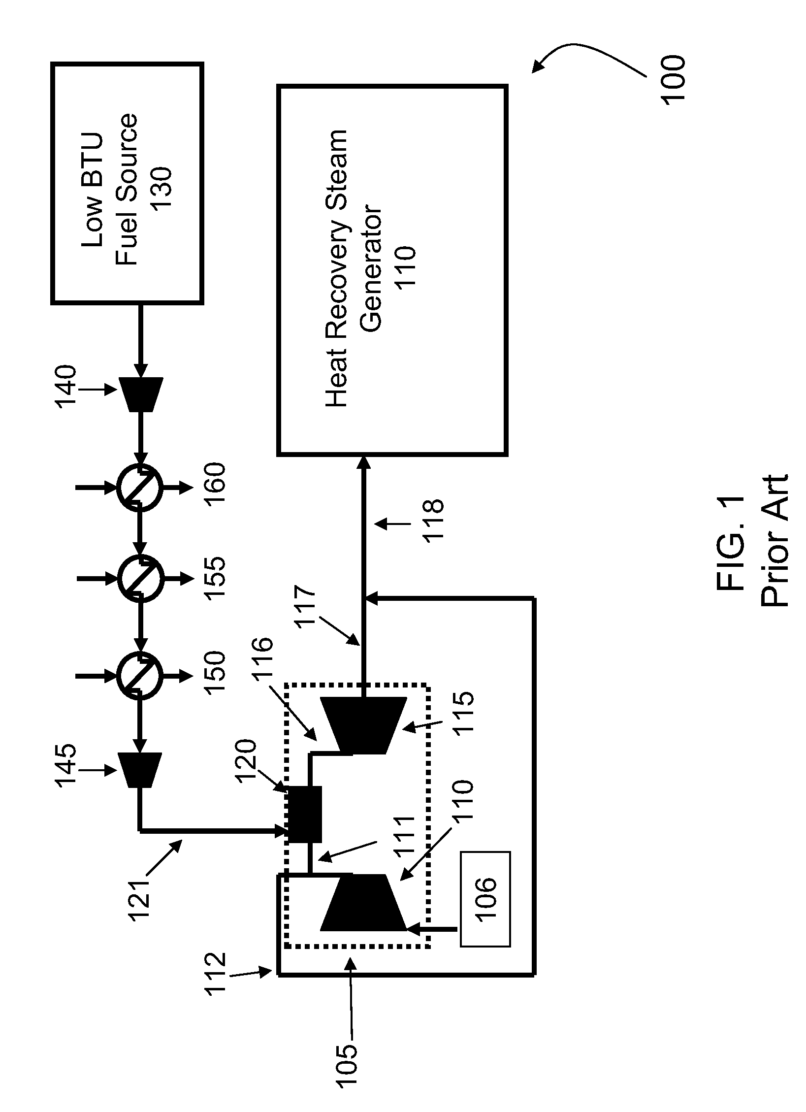
[0017]FIG. 1 illustrates a conventional combined cycle system 100 with a gas turbine topping cycle 105 thermally coupled to a steam turbine bottoming cycle or, as illustrated in the diagram, heat recovery steam generator (“HRSG”) system 110. Simple cycle gas turbine system 105 includes a compressor 110, a turbine component 115, a combustor 120, and a load (e.g., a generator) arranged on a single rotor or shaft (not pictured). Combustor 120 receives fuel via stream 121, and compressed air from compr...


PUM


Abstract

Embodiments of the invention can provide systems, methods, and an apparatus for modifying the power output and efficiency of a combined cycle power plant. According to one embodiment where a combined cycle power plant includes a compressor, a gas turbine, a combustor, and a heat recovery steam generator, excess air from the compressor can be extracted and expanded to generate power. The expanded air can then be mixed with at least one combustible fuel to generate a heated combustion product. The heated combustion product can be mixed with exhaust gas from the gas turbine to increase the temperature of the exhaust gas prior to introduction to the heat recovery steam generator. This increase in temperature of the exhaust gas from the gas turbine provides additional energy for generating steam and power and improves performance of the heat recovery steam generator.

Description

FIELD OF THE INVENTION[0001]The invention relates to a combined cycle power plant, and more specifically to systems, methods, and an apparatus for modifying power output and efficiency of a combined cycle power plant.BACKGROUND OF THE INVENTION[0002]A combined cycle power plant can use a combination of a gas turbine and a steam turbine to produce electrical power. In a combined cycle power plant, a gas turbine cycle can be operatively combined with a steam turbine cycle by way of a heat recovery steam generator (“HRSG”).[0003]In a combined cycle power plant, the gas turbine cycle can be referred to as a topping cycle, and the steam turbine cycle can be referred to as a steam bottoming cycle. The gas turbine topping cycle typically has at least one compressor, at least one combustor, and an expander. In the compressor, air is pressurized to mix with a fuel for burning. The air / fuel mixture is then burned in the combustor. This operation results in a high temperature combustion produc...

Claims


Application Information

Patent Timeline
Patent Type & Authority Applications(United States)
IPC IPC(8): F02C9/00F02C7/00
CPCF01K23/064Y02E20/16F02C6/18F01K23/10
Inventor SAHA, RAJARSHIL., SHIVAPRASADMAZUMDER, INDRAJITGOPALKRISHNA, VINOD KUMAR BAIKAMPADY
Owner GENERAL ELECTRIC CO
Why Eureka
Try Eureka