Cryogenic rectification method

Inactive Publication Date: 2010-09-30
PRAXAIR TECH INC
View PDF8 Cites 25 Cited by
  • Summary
  • Abstract
  • Description
  • Claims
  • Application Information

AI Technical Summary

Benefits of technology

[0009]The high pressure column and the low pressure column are each configured to separate the nitrogen from the oxygen by contacting an ascending vapor phase becoming evermore rich in nitrogen as it ascends with a descending liquid phase becoming evermore rich in oxygen as it descends. The ascending vapor phase is contacted with the descending liquid phase, in each of the high pressure column and the low pressure column, within mass transfer contacting elements peripherally bounded by a column diameter selected such that a maximum superficial vapor velocity produced by the ascending vapor phase results in a vapor capacity factor below an operational limit at which flooding would otherwise occur within the mass transfer contacting elements in which the maximum superficial vapor velocity occurs. The column diameter of the low pressure column is substantially equal to or less than the diameter of the high pressure column. It is to be noted that as used herein and in the claims, the term, “superficial vapor velocity” means a vapor velocity

Problems solved by technology

Since there exists heat leakage into such process and warm end losses in the main heat exchanger, refrigeration is imparted to the process.
However, for a given reflux rate of liquid, there exists a limitation on the superficial vapor velocity produced by ascending vapor of the vapor phase at which the vapor resists the downflowing liquid progress in the column in a condition known as flooding.
The problem with having a low pressure column with a larger diameter than the high pressure column is that shipment costs of the column system from the fabricator to the site at which the plant

Method used


Image

  • Cryogenic rectification method
  • Cryogenic rectification method
  • Cryogenic rectification method

Examples


Embodiment Construction

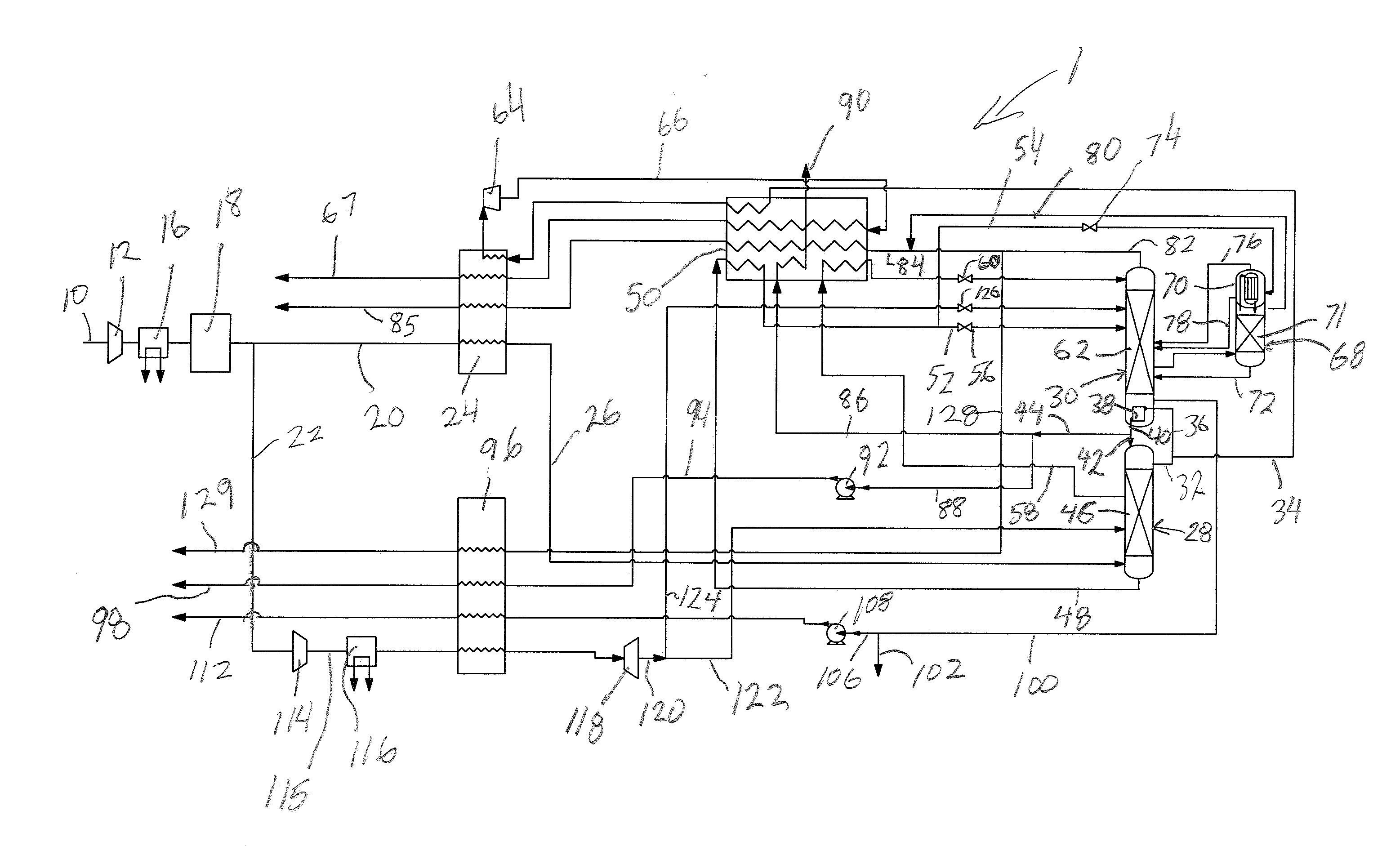
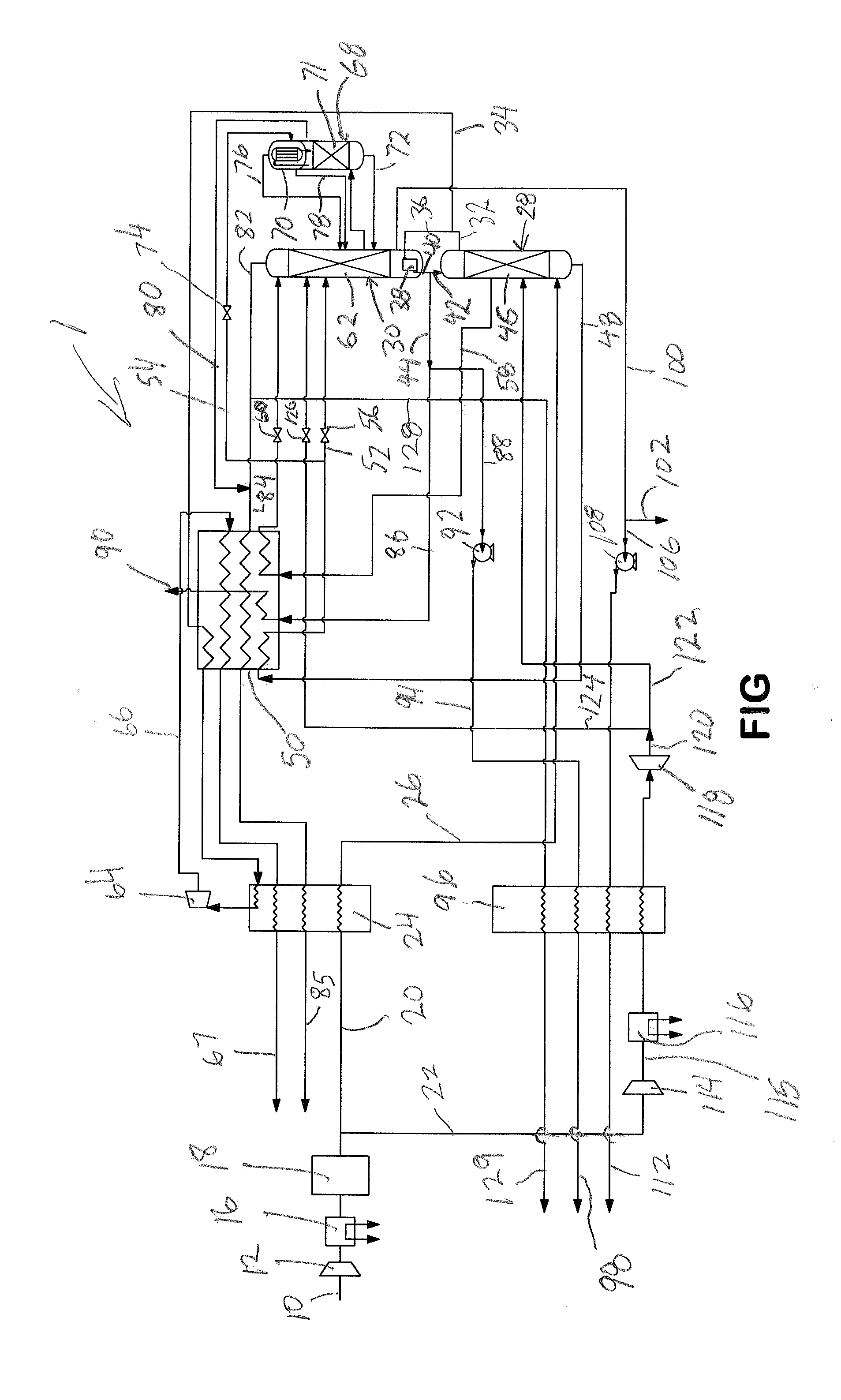
[0017]With reference to the Figure, an air separation plant 1 is illustrated for carrying out a method in accordance with the present invention for rectifying a feed stream 10 that contains oxygen, nitrogen and argon. Feed stream 10 can be air or other air derived stream that is obtained from some other process. It is understood that air separation plant 1 is described herein for exemplary purposes.

[0018]The feed stream 10 is compressed by a compressor 12 and after removing the heat of compression within an aftercooler 16, the compressed feed stream 10 is purified within a purification unit 18 having beds of adsorbent to remove higher boiling impurities such as water vapor, carbon dioxide and hydrocarbons. The resulting compressed and purified feed stream 10 is then divided into a first part 20 and a second part 22.

[0019]The first part 20 is cooled within a first heat exchanger 24 and then fully cooled to a temperature suitable for its rectification. The resulting cooled stream 26 i...


PUM


Abstract

The present invention provides a method of rectifying an oxygen, nitrogen and argon containing feed stream that employs high and low pressure columns and an argon column. Refrigeration is imparted through turboexpansion of a nitrogen-rich vapor stream withdrawn from the high pressure column. The nitrogen-rich vapor stream has a sufficiently high flow rate that the flow of both vapor and liquid within the low pressure column is decreased to such an extent that the diameter of the low pressure column can be made substantially equal to or less than that of the high pressure column. The use of the argon column allows recovery of the oxygen to be increased over that which would otherwise be obtained given the draw of the nitrogen-rich vapor. The argon column can be an argon rejection column in which the separated argon is discarded as waste.

Description

FIELD OF THE INVENTION[0001]The present invention relates to a method of rectifying an oxygen, nitrogen and argon containing mixture in a cryogenic rectification process utilizing a high pressure column, a low pressure column and an argon column. More particularly, the present invention relates to such a method in which the flow rate of nitrogen-rich vapor produced in a high pressure column is selected to reduce the vaporization of an oxygen-rich liquid column bottoms produced in the low pressure column and thereby to permit the diameter of the low pressure column to be sized substantially equal to or less than that of the high pressure column.BACKGROUND OF THE INVENTION[0002]Air is rectified into oxygen, nitrogen and argon component by a process known as cryogenic rectification. In such a process the air, or other gas containing oxygen, nitrogen and argon, is compressed, purified of higher boiling contaminants such as water vapor, carbon dioxide and hydrocarbons. At least part of t...

Claims


Application Information

Patent Timeline
IPC IPC(8): F25J3/04
CPCF25J3/04084F25J3/0409F25J3/04218F25J3/0423F25J3/04309F25J2240/22F25J3/04412F25J3/04678F25J2240/10F25J2245/58F25J3/04387
Inventor PROSSER, NEIL MARKZHANG, WEI
Owner PRAXAIR TECH INC
Why Eureka
Try Eureka