Rotary ultrasonic sealing

Inactive Publication Date: 2010-09-30
LAVAZZA PROFESSIONAL NORTH AMERICA LLC
View PDF11 Cites 8 Cited by
  • Summary
  • Abstract
  • Description
  • Claims
  • Application Information

AI Technical Summary

Benefits of technology

[0019]Suitably, the apparatus further comprises one or more setting rollers, configured to apply a light compression to the sealed web after it has exited the sonotrode gap in order to aid fusion between the web layers during cooling. The roller has the benefit of improving weld homogeneity and strength, particularly for non-woven materials such as filter materials used inside beverage sachets. The settin

Problems solved by technology

However, difficulties arise even with this arrangement.
However, there is a limit as to how much ultrasonic energy can be delivered by a sonotrode actuator.
If the roller rotates too quickly, then each weld would be incomplete, i.e. a reliable seal would not be achieved because insufficient energy was delivered to the web

Method used


Image

  • Rotary ultrasonic sealing
  • Rotary ultrasonic sealing
  • Rotary ultrasonic sealing

Examples


Embodiment Construction

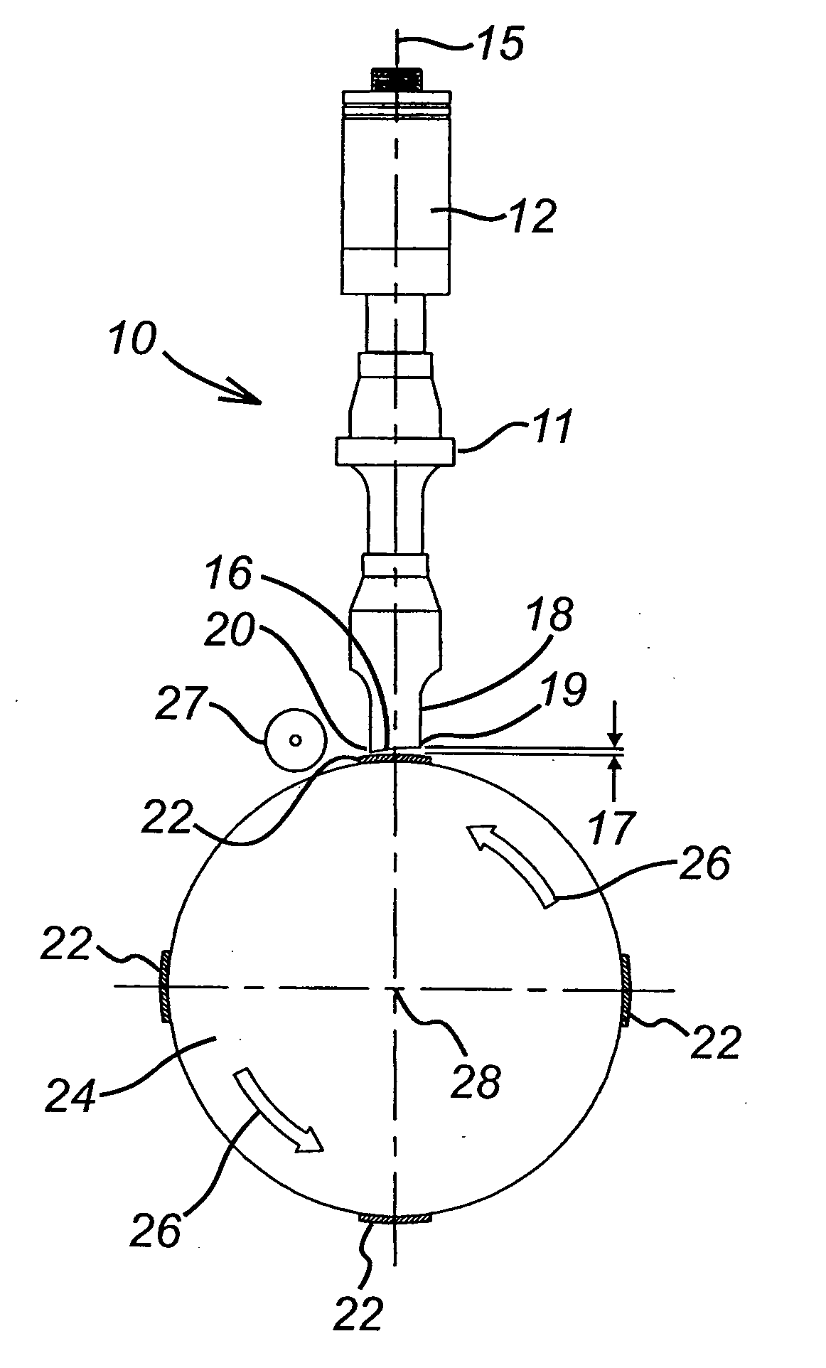
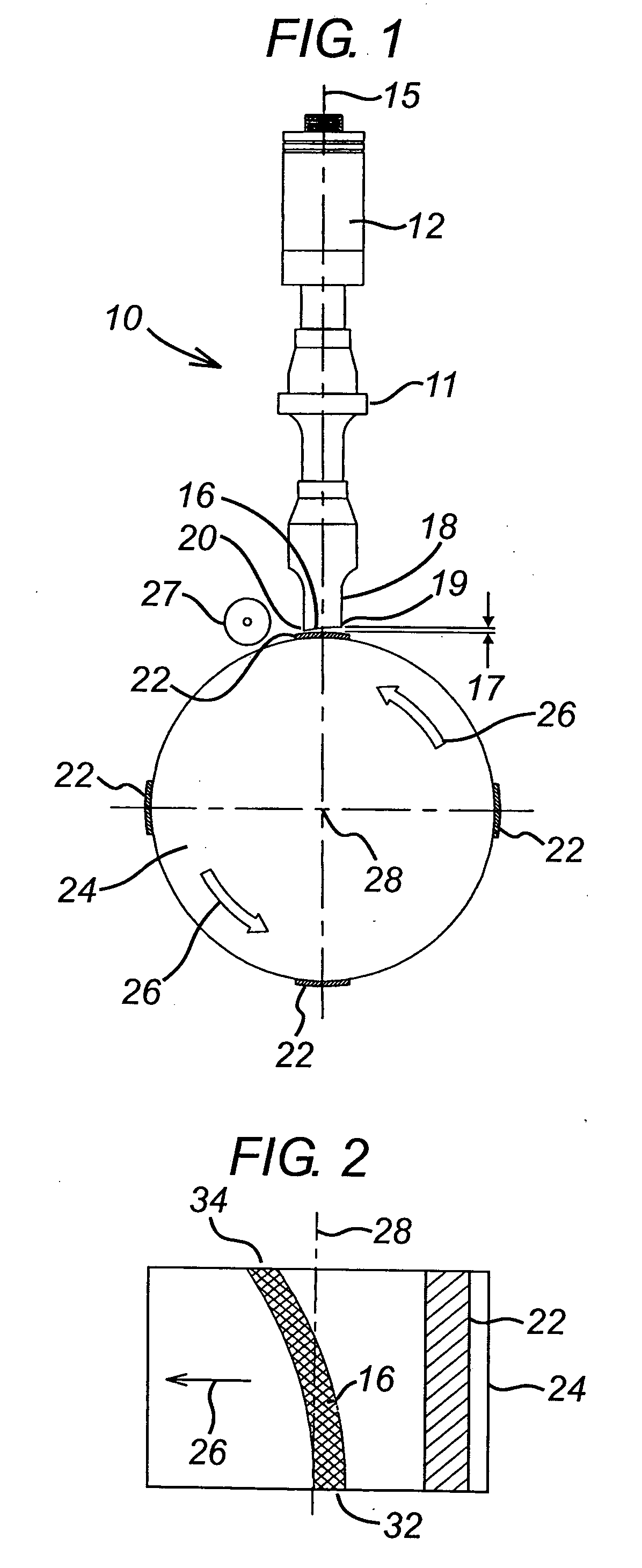
[0026]Referring to FIG. 1, the apparatus comprises a sonotrode assembly 10 and a rotating anvil 24. The sonotrode assembly 10 comprises an ultrasonic actuator 12 that is coupled to a booster or number of boosters 11 coupled to sonotrode head 18. The sonotrode head 18 has an elongate, profiled sealing end face 16 that faces the rotating anvil 24. The anvil 24 comprises a roller provided with four raised portions 22 of substantially constant width (measured along the circumference of the anvil) and height (measured radially from the center of the roller) extending along its outer surface parallel to the axis of rotation 28 of the anvil. In the configuration shown in the drawing, it can be seen that a sealing gap 17 is intermittently defined between the sonotrode end face 16 and the outer surface of each raised portion 22 of the roller anvil.

[0027]The end face 16 is profiled to provide a sealing gap 17 between the sonotrode and the anvil 24. The end face 16 of the sonotrode is profiled...


PUM

PropertyMeasurementUnit
Lengthaaaaaaaaaa
Thicknessaaaaaaaaaa
Speedaaaaaaaaaa

Abstract

The invention is an apparatus for forming an ultrasonic weld that includes a sonotrode having an ultrasonic actuator coupled to an elongate sealing end face for delivering ultrasonic energy to the webs in the sealing gap and a rotating cylindrical anvil having at least one raised portion extending longitudinally along an outer surface thereof. The raised portion has a radially outer surface, whereby the sealing gap is defined intermittently between the end face of the sonotrode and the radially outer surface of the raised portion of the anvil as the raised portion rotates past the end face of the sonotrode. The elongate sealing end face of the sonotrode has a substantially helical surface, whereby the sealing gap travels helically along the surface as the raised portion of the anvil cylinder rotates past the end face of the sonotrode.

Description

CROSS-REFERENCE TO RELATED APPLICATIONS[0001]This application is a national stage filing of PCT / GB2007 / 004512 filed Nov. 26, 2007 which claims priority from Application 0623648.3 filed on Nov. 27, 2006 in the United Kingdom.TECHNICAL FIELD[0002]The present invention relates to an apparatus and method for rapidly creating transverse seals between at least two superimposed flexible webs of sheet material, by using ultrasonic energy to bond the flexible webs together.BACKGROUND OF THE INVENTION[0003]It is known to use ultrasonic devices for creating a sealing joint between two or more flexible webs of sheet material. Such procedures can be used during the manufacture of packets for packaging materials therein. See, for example, U.S. Pat. No. 6,824,632. This document discloses a sonotrode and an opposed anvil. The webs to be joined together are passed between them in an aligned manner to compress the webs together, and at desired positions, the webs are then sealed together by activatin...

Claims


Application Information

Patent Timeline
IPC IPC(8): B32B37/02
CPCB29C65/086Y10T156/1737B29C66/221B29C66/2442B29C66/345B29C66/346B29C66/80B29C66/81415B29C66/81419B29C66/81427B29C66/83411B29C66/83511B29C66/929B29C66/939B29K2105/0854B29L2031/14B29C66/0322B29C66/93451B29C66/92611B29C66/91643B29C66/81433B29C66/93441B29C65/00B29C66/431B29C66/81413B29C66/43B29C66/1122B29C65/08
Inventor BLANCHARD, DANIELWICKS, DAVIDMONTOYA, MICHEL
Owner LAVAZZA PROFESSIONAL NORTH AMERICA LLC
Why Eureka
Try Eureka