Piezoelectric Generator

a generator and piezoelectric technology, applied in piezoelectric/electrostrictive/magnetostrictive devices, piezoelectric/electrostriction/magnetostriction machines, electrical equipment, etc., can solve the problems of increasing assembly man-hour, poor durability, and poor power generation efficiency, so as to reduce curvature, increase the rate of power generation, and effect of effective power generation

Inactive Publication Date: 2010-09-30
RION COMPANY +1
View PDF12 Cites 46 Cited by
  • Summary
  • Abstract
  • Description
  • Claims
  • Application Information

AI Technical Summary

Benefits of technology

[0029]According to the present invention, the elastic plate deforms in a big way from a position convexed upward to a position convexed downward, causing a compression strain in the piezoeletric element over its entirety as this deformation progresses, thus generating electric charges and hence causing an effective power generating action. Next, as the load is removed, the elastic energy stored in the elastic system with the piezoelectric element and the elastic plate is released, while the piezoelectric element is agitated again by impact vibrations caused by the releasing process of the elastic energy, and another power generation action occurs at this point as well. In other words, for example, if a piezoelectric element is glued onto the surface of the elastic plate which is affixed at both ends to form an upward convex shape, and the elastic plate is deformed to create a downward convex shape, the entire piezoelectric element will be compressed, rather than both ends having tensile deformations and the center portion having a compressive deformation, so that only a constant bending moment occurs without causing any electric charge cancellation, thus increasing the rate of power generation.
[0030]Said elastic plate is shaped substantially rectangular and is bent like an arc as mentioned before, with its peak point located a little off the center in the lengthwise direction thus having a flat area with a reduced curvature away from the peak, so that if such a flat area is used as a location for gluing the piezoelectric element, it not only makes the gluing process easier but also causes less flexing thus minimizing the peeling of the piezoelectric element. Moreover, such a constitution provides a space for allowing the elastic plate to deform relative to the base plate so that the piezoelectric element can be located in the area where it can be easily deformed to store the elastic energy as it is subjected to a load from above.
[0031]Also, in case of the elastic plate bent in an arc shape, the spring constant when a pressure is applied to the peak point P is several tens of times larger than the spring constant of a straight beam affixed on both ends, so that the elastic energy that can be stored as expressed in the aforementioned formula (1) becomes larger, thus causing a larger distortion of the piezoelectric ceramic plate caused by said vibrations, and hence a amount of power generation become larger as well.
[0032]Furthermore, taking advantage of the fact that the peak point moves toward the fulcrum point of the spacer member as the load increases, it is possible to adjust the spacer member to be located exactly beneath the loading point when the load exceeds a certain load, which functions as a protection mechanism for the piezoelectric element by limiting the elastic deformation not to proceed further once such a state is reached.
[0033]The piezoelectric element is made as a water-resistant, mechanically robust, non-destructible and simple component by constituting it of a flat piezoelectric ceramic plate and coating said piezoelectric ceramic plate with a water-resistant material. Using an organic material such as rubber or elastomer as a water resistant material makes it easier to fabricate it.

Problems solved by technology

However, these power generating devices have either piezoelectric ceramics pinched between floor plates or installed on the steps of stairs, so that power generating efficiency is not too good, as the strains developed in the piezoelectric ceramics are limited because of limited elastic modulus of the piezoelectric ceramics.
When such a device is installed on the sidewall, it becomes a three dimensional arrangement and can be a cause of an increase of assembling man-hour.
In the latter power generating system, the load bearing area is small so that the generated strain is limited and may cause a problem in the power generating efficiency, Such a power generating system can be considered a kind of an elastic system, and that the size of the energy E to be stored in the elastic system can be defined as:
However, it was confirmed that such an approach can lead to the breakage of the piezoelectric bimorph element and result in a poor durability as it increase the strain caused in the affixing area.
Moreover, although the compliance can be increased by using a double-side-supported beam type piezoelectric bimorph element, i.e., by supporting both ends of the piezoelectric bimorph element from beneath to receive a load applied from above a supporting condition, it was learned that instability of the affixing becomes inevitable, thus being unable to achieve a stable power generating performance in such a case.
It was further revealed that although the compliance can be maximized by supporting a piezoelectric bimorph element at both ends, it was learned that such an arrangement is undesirable as it develops positive and negative bending moments on the piezoelectric bimorph element when a load is applied, thus causing cancellation of electric charges, resulting in a reduced power generation.
Also, in case of the elastic plate bent in an arc shape, the spring constant when a pressure is applied to the peak point P is several tens of times larger than the spring constant of a straight beam affixed on both ends, so that the elastic energy that can be stored as expressed in the aforementioned formula (1) becomes larger, thus causing a larger distortion of the piezoelectric ceramic plate caused by said vibrations, and hence a amount of power generation become larger as well.

Method used


Image

  • Piezoelectric Generator
  • Piezoelectric Generator
  • Piezoelectric Generator

Examples


example

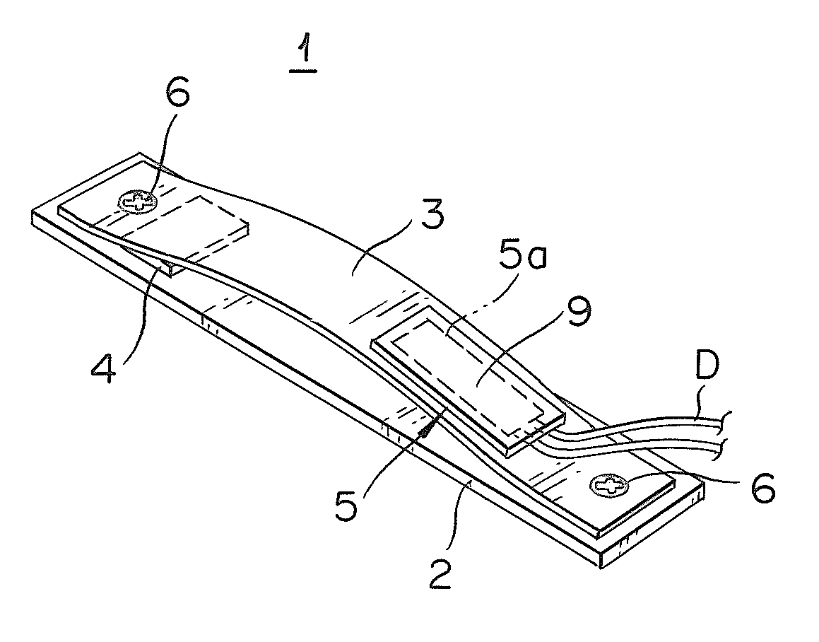
[0058]The piezoelectric element 5 has a silver electrode formed on the top surface of a rectangular piezoelectric ceramic plate 5a (35 mm×18 mm×0.6 mm) and is polarization treated in the thickness direction. As the piezoelectric material, a material with an electromechanical coupling factor k31 of over 30%, a relative dielectric constant e r of 1800, and a mechanical quality coefficient Qm of approximately 1000 is used.

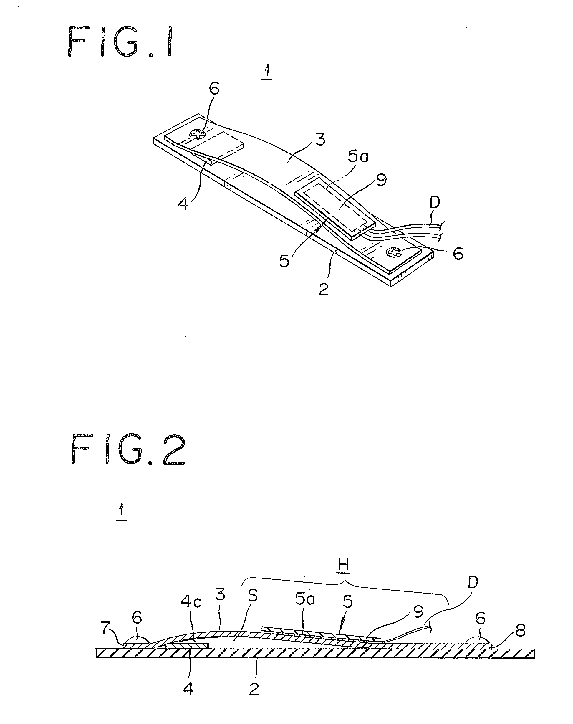
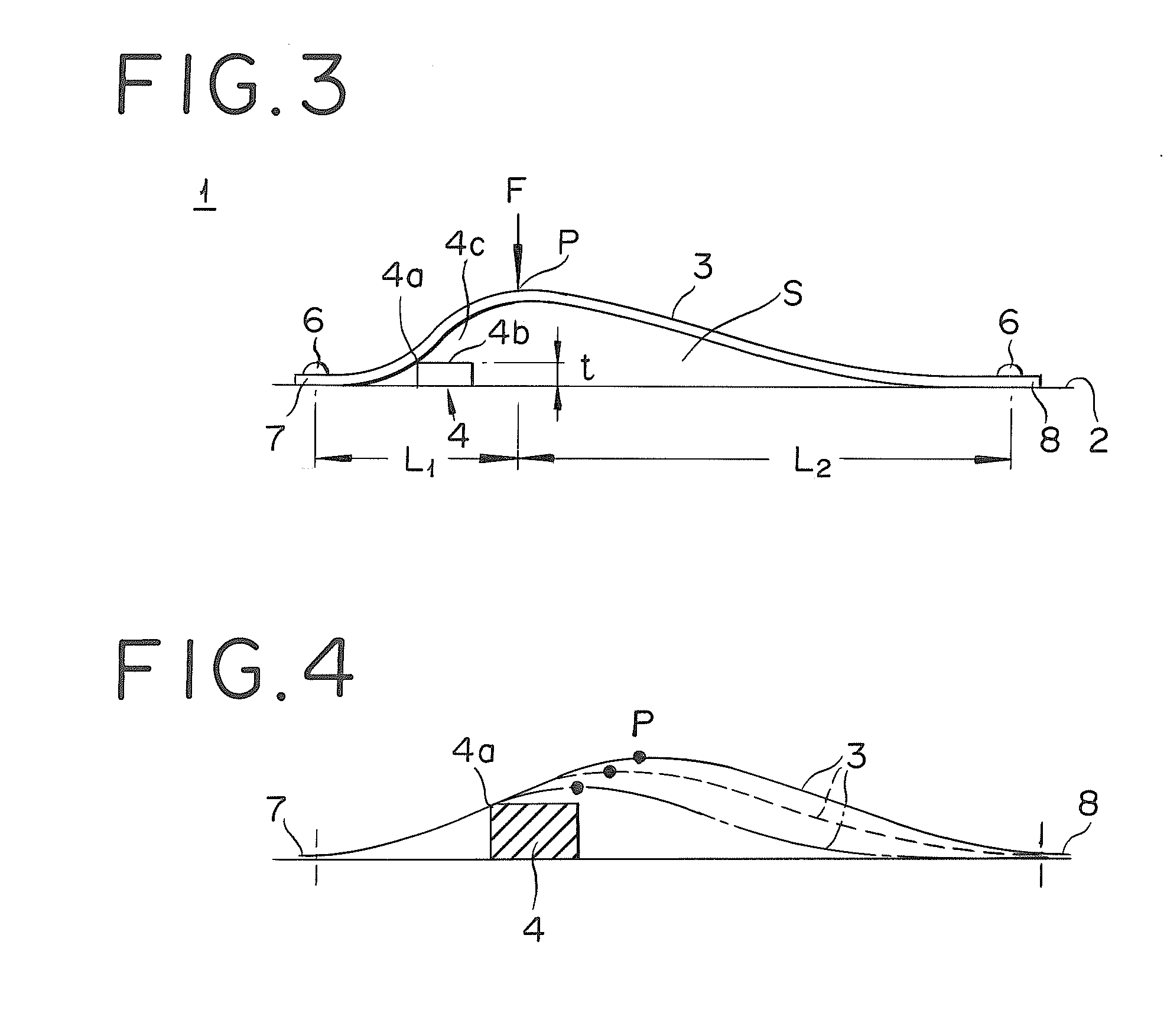
[0059]The elastic plate 3 (130 mm×30 mm×1.6 mm) used was a glass epoxy resin FR-4 formed into a gradually curved shape. The spacer member 4 (30 mm×15 mm×2 mm) used was an iron block.

[0060]If an electrically conductive material such as a metal is used as the elastic plate 3, it is possible to get conductivity by connecting with one of the electrodes of the piezoelectric element 5 and to take out the lead wire D of one of the terminals from the top surface of the base plate 2, but the two lead wires D are connected as shown in FIG. 1 using a glass epoxy elastic plate 3 ...


PUM


Abstract

The piezoelectric generator is characterized by providing a spacer member in the vicinity of a fixed end of an elastic plate mounted on a base plate by means of affixing both ends in such a way as to prevent the elastic plate not to be deformed unnecessarily when a load is applied to the elastic plate from above, so that a piezoelectric ceramic plate glued onto the elastic plate generates electric power by the elastic plate's deformation.

Description

BACKGROUND[0001]1. Technical Field[0002]The present invention relates to a piezoelectric generator for converting mechanical loads and vibrations to the strains of a piezoelectric material and take out electrical energy.[0003]2. Description of Related Art[0004]There have been developments of various techniques lately for using electrical energy generated by the strains of piezoelectric materials caused by external forces and vibrations. It is a common practice to use a piezoelectric generator in order to obtain electrical energy from a piezoelectric material. A piezoelectric generator is essentially a unit that causes strains in a piezoelectric device by means of impacting it with an impacting member formed as a metallic sphere or a ceramic sphere, or by fixing one end of a piezoelectric element and pressing or vibrating the other end of it. The electric energy obtained by a piezoelectric generator is used for illuminating a light emitting diode directly, or stored in a capacitor or...

Claims


Application Information

Patent Timeline
Patent Type & Authority Applications(United States)
IPC IPC(8): H02N2/18
CPCH01L41/1134H01L41/053H10N30/88H10N30/304
Inventor NAGASHIMA, SUSUMUMATSUMURA, RYOTARO
Owner RION COMPANY
Why Eureka
Try Eureka