Near-field Raman spectroscopy

a raman spectroscopy and near-field technology, applied in the field of spectroscopy, can solve the problems of low resolution and inability to use water-sensitive samples

Inactive Publication Date: 2010-09-30
RENISHAW PLC
View PDF6 Cites 47 Cited by
  • Summary
  • Abstract
  • Description
  • Claims
  • Application Information

AI Technical Summary

Benefits of technology

[0014]In one preferred embodiment, the micro-particle is held on or just above the surface by an optical trapping or “optical tweezer” technique. We have found that the spatial resolution obtained using this technique in the preferred embodiment is about 100 nm, much smaller than that obtained by SIL.

Problems solved by technology

This technique has the drawback that there is Brownian motion that can lower the resolution.
Also, the preferred embodiment traps the micro-particle in a liquid, preferably water, and so it cannot be used for water sensitive samples.

Method used


Image

  • Near-field Raman spectroscopy
  • Near-field Raman spectroscopy
  • Near-field Raman spectroscopy

Examples


Embodiment Construction

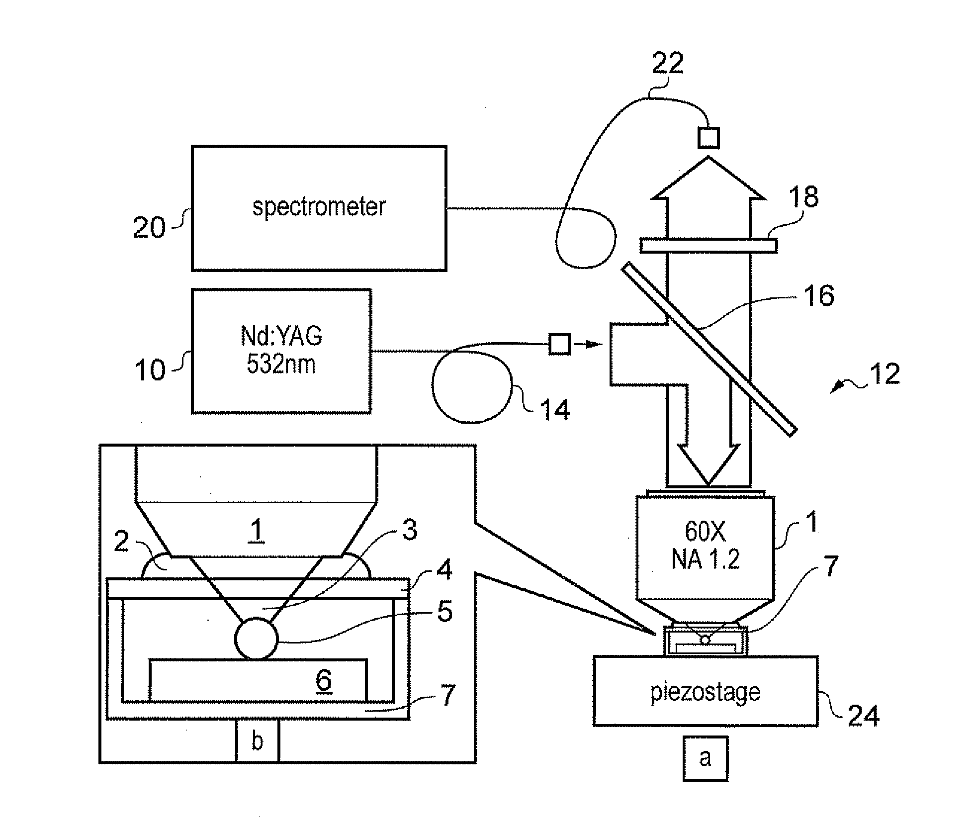
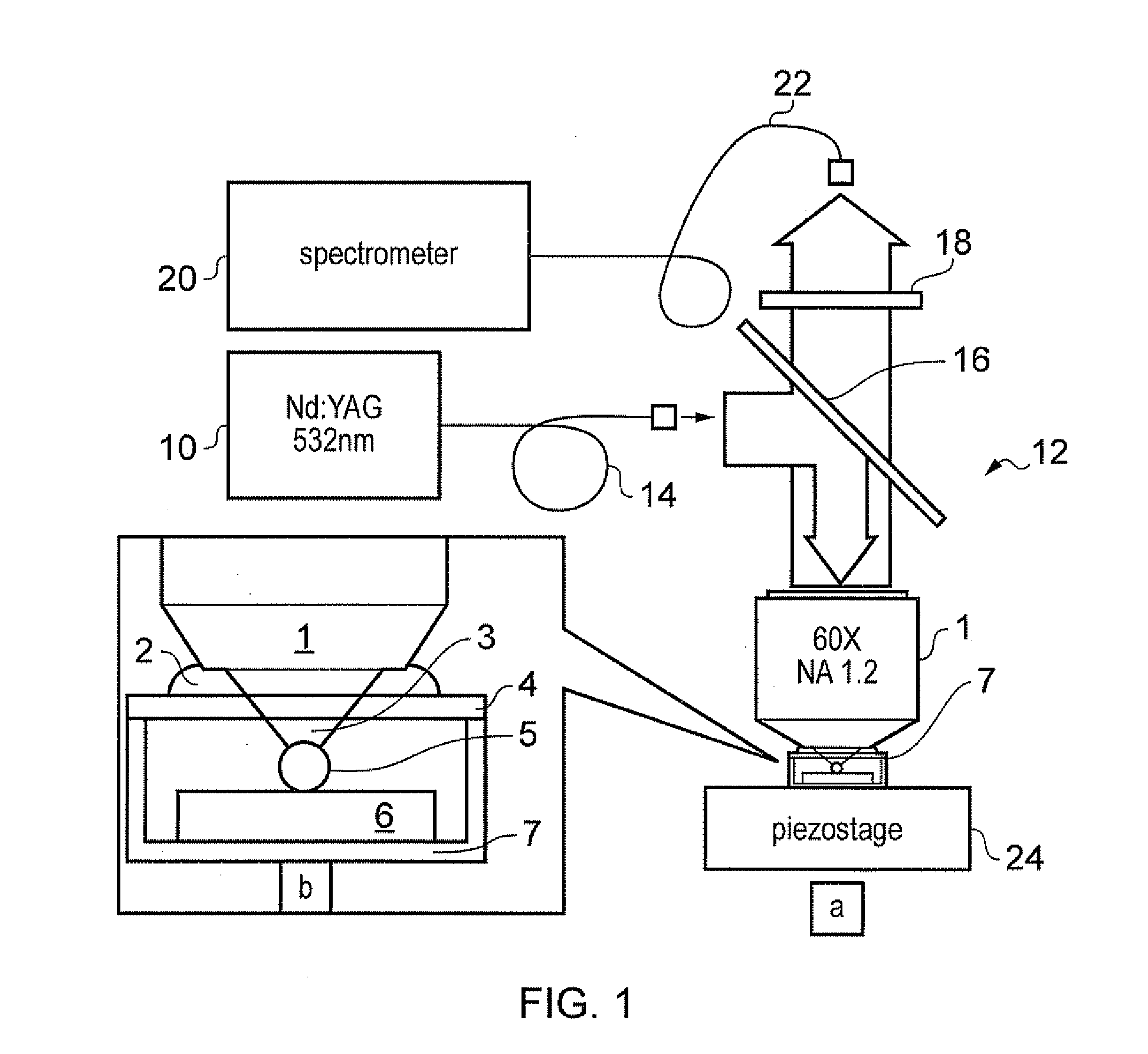
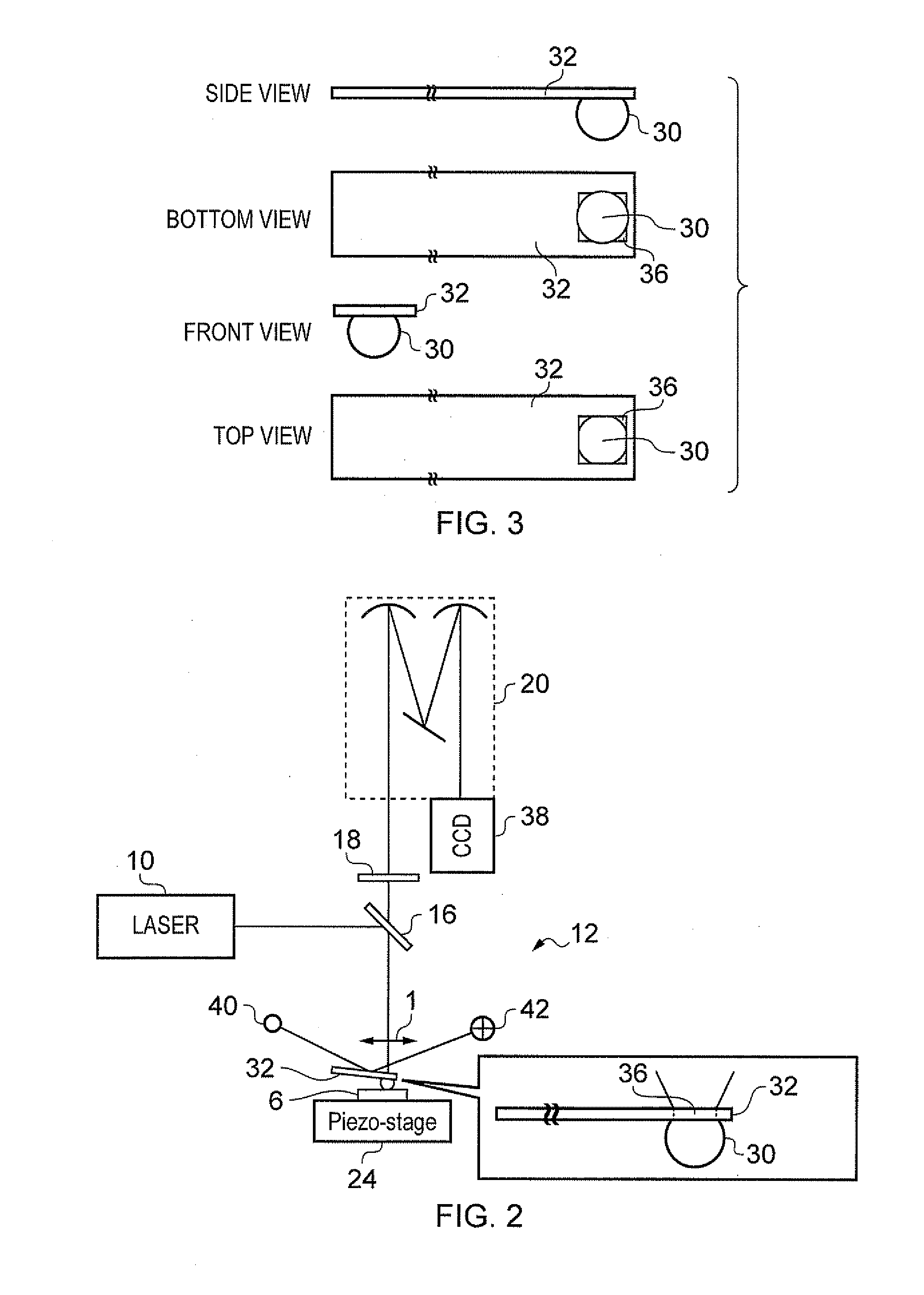
[0022]We have developed a new approach to near field, whereby the laser is focused to a spot size smaller than diffraction limit by a dielectric microsphere. In the embodiment of FIG. 1, besides being used as the excitation source for Raman spectroscopy, the incident laser beam (linearly polarized Gaussian TEM00 mode) is also used to hold the microsphere just above the sample surface, through the well-known optical tweezer mechanism. See Ashkin, A., “Applications of laser radiation pressure”, Science 210, 1081-1088 (1980) and Ashkin, A. “Optical trapping and manipulation of neutral particles using lasers”, Proc. Natl. Acad. Sci. USA 94, 4853-4860 (1997).

[0023]The diameter of the dielectric microsphere is comparable to the wavelength of the laser. Simulation studies have shown that sub-diffraction limited focusing can thereby be achieved, with improved spatial resolution due to the near field effect. See Xu Li et al, “Optical analysis of nanoparticles via enhanced backscattering faci...


PUM


Abstract

Near-field Raman imaging is performed by holding a dielectric microsphere (e.g. of polystyrene) on or just above the surface of a sample in a Raman microscope. An illuminating laser beam is focused by the microsphere so as to produce a near-field interaction with the sample. Raman scattered light at shifted wavelengths is collected and analysed. The microsphere may be mounted on a cantilever of an atomic force microscope or other scanning probe microscope, which provides feedback to hold it in position relative to the sample surface. Alternatively, the microsphere may be held on the sample surface by an optical tweezer effect of the illuminating laser beam.

Description

CROSS-REFERENCE TO RELATED APPLICATION[0001]This application claims priority from U.S. Provisional Patent Application No. 61 / 202,698, filed 27 Mar. 2009, which is incorporated herein by reference.FIELD OF THE INVENTION[0002]This invention relates to spectroscopy, for example spectroscopy using Raman, photoluminescence (PL) or other inelastically scattered light. It also relates to microscopy using near-field effects.DESCRIPTION OF PRIOR ART[0003]Raman and photoluminescence (PL) microscopy (Raman microscopy for short) has been used extensively for material characterization in research and industry. They are examples of spectroscopic techniques using light which is inelastically scattered by the sample. These techniques provide information on the composition, chemical bonding, electronic and atomic structures and strain / stress of the sample. This information cannot be obtained / or easily obtainable by other conventional microscopic techniques such as atomic force microscopy (AFM), scan...

Claims


Application Information

Patent Timeline
Patent Type & Authority Applications(United States)
IPC IPC(8): G01J3/44
CPCB82Y20/00B82Y35/00G01J3/02G01J3/0208G01J3/44G02B27/141G01N2021/656G01Q30/02G01Q60/22G02B21/26G02B21/33G01N21/658G01N2201/0639
Inventor SHEN, ZEXIANGKASIM, JOHNSONYOU, YUMENGYU, TING
Owner RENISHAW PLC
Why Eureka
Try Eureka