
Phase error correction in a coherent receiver

a phase error and coherent receiver technology, applied in the field of signal receivers, can solve the problems of significant transmission penalty, affecting the processing speed of the signal, and the difference between the in-phase (i) and quadrature (q) components, and achieve the effect of reducing the processing delay

Active Publication Date: 2010-09-30
ALCATEL LUCENT SAS
View PDF16 Cites 14 Cited by
  • Summary
  • Abstract
  • Description
  • Claims
  • Application Information

AI Technical Summary

Benefits of technology

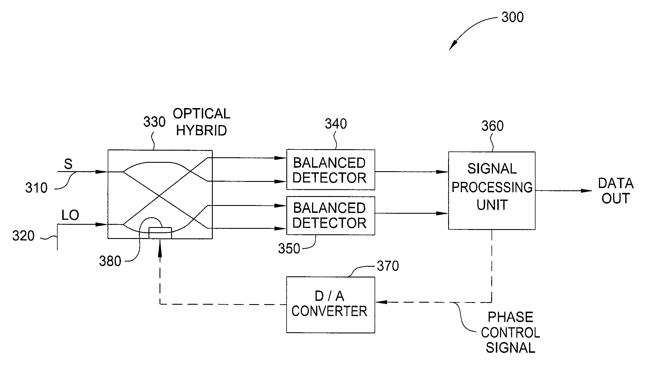
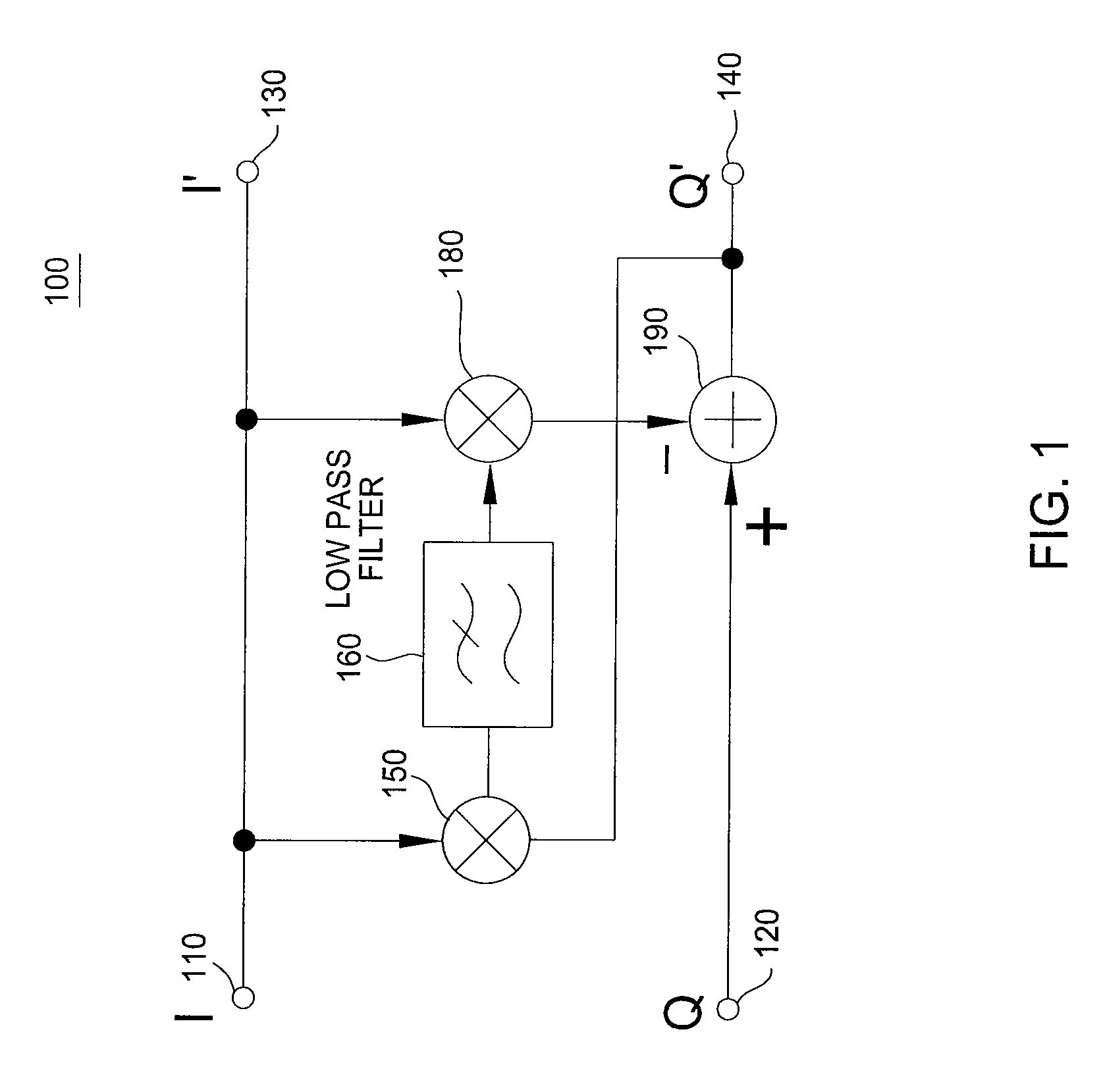
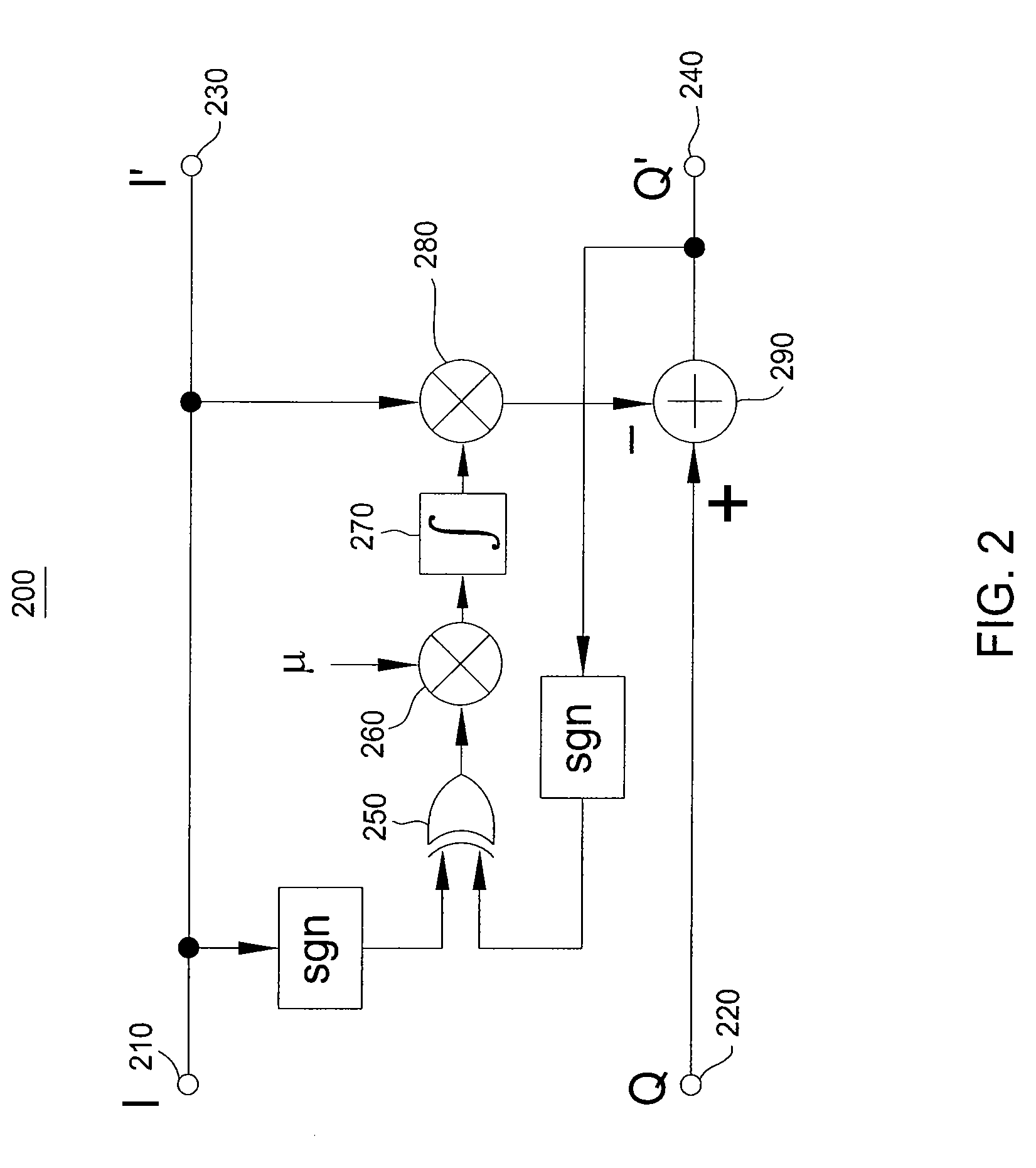
The present invention provides an improved and simplified way to correct phase errors in signals received by a coherent receiver. This can be done with minimal circuitry and processing delay. The invention includes an optical hybrid with an adjustable phase control mechanism controlled by a phase correction signal, an exclusive or-gate and integrator for constructing a phase error signal, and a multiplier and low pass filter for correlating the in-phase and quadrature components of an input signal to derive a phase error signal. Overall, the invention allows for more efficient and effective correction of phase errors in signals.

Problems solved by technology

Due to imperfections in manufacturing, temperature effects and other impairments of the optical hybrid in particular, the phase difference between the in-phase (I) and quadrature (Q) components may deviate from the ideal 90 degree separation.
In many systems the phase error results in a significant transmission penalty characterized by a higher bit error rate (BER) and, in optical systems, higher required optical signal to noise ratio (OSNR) for a given BER.
However, such techniques have been complicated.

Method used


Image

  • Phase error correction in a coherent receiver
  • Phase error correction in a coherent receiver
  • Phase error correction in a coherent receiver

Examples


Embodiment Construction

[0017]Embodiments of the invention enable efficient detection and correction of phase errors exhibited by an input signal in a coherent receiver. In particular, the embodiments provide a novel and simple algorithm for calculating and correcting a phase error.

[0018]For ease of reference, embodiments will be described in particular relation to an optical hybrid receiver. However, it is to be understood that the embodiments are not so limited in scope and in application. For example various types of phase encoded signals with in-phase and quadrature phase components may also exhibit deviations from the ideal 90 degree separation. Signals that may be affected by a phase error include radar signals, wireless telephone and data signals, satellite and cable television signals, fiber-optic communications signals and electrical data signals. Such signals may be encoded by phase shift keying (PSK), differential phase shift keying (DPSK) or quadrature phase shift keying (QPSK), for example, or...


PUM


Abstract

A method and apparatus for correcting of phase errors in a coherent optical receiver are disclosed. Embodiments include a method for calculating a phase error between in-phase and quadrature-phase component signals, multiplying the phase error by one of the component signals and subtracting the result from the other component signal to output a corrected signal.

Description

FIELD OF THE INVENTION[0001]The present invention relates to signal receivers and, more specifically, to correcting the phase error exhibited by a phase encoded signal.BACKGROUND OF THE INVENTION[0002]Polarization multiplexed receivers as well as optical hybrids have been described in detail in Kaneda, et al., “System and Method for Receiving Coherent, Polarization-Multiplexed Optical Signals,” Patent Application Publication No. US 2007 / 0297806 A1, Dec. 27, 2007, which is incorporated herein by reference in its entirety. Due to imperfections in manufacturing, temperature effects and other impairments of the optical hybrid in particular, the phase difference between the in-phase (I) and quadrature (Q) components may deviate from the ideal 90 degree separation. Such a deviation is referred to as a phase error.[0003]In many systems the phase error results in a significant transmission penalty characterized by a higher bit error rate (BER) and, in optical systems, higher required optica...

Claims


Application Information

Patent Timeline
Patent Type & Authority Applications(United States)
IPC IPC(8): H04B10/06H04L27/00
CPCH03D2200/0082H04B10/60H04B10/613H04L2027/0069H04L27/223H04L2027/0024H04L2027/0057H04B10/6165
Inventor KANEDA, NORIAKILEVEN, ANDREAS B.
Owner ALCATEL LUCENT SAS
Learn More