Motor-driven supercharger

a supercharger and motor technology, applied in the direction of positive displacement liquid engines, pumps, machines/engines, etc., can solve the problems of reducing the amount of compressed air supplied to the engine, low cooling performance, and inability to efficiently cool a whole stator, so as to achieve efficient cooling of a whole stator

Active Publication Date: 2010-09-30
IHI CORP
View PDF42 Cites 37 Cited by
  • Summary
  • Abstract
  • Description
  • Claims
  • Application Information

AI Technical Summary

Benefits of technology

[0019]The present invention is made for solving the problem mentioned above. In other words, an object of the present invention is to provide a m

Problems solved by technology

Accordingly, there is a problem that a cooling performance is low.
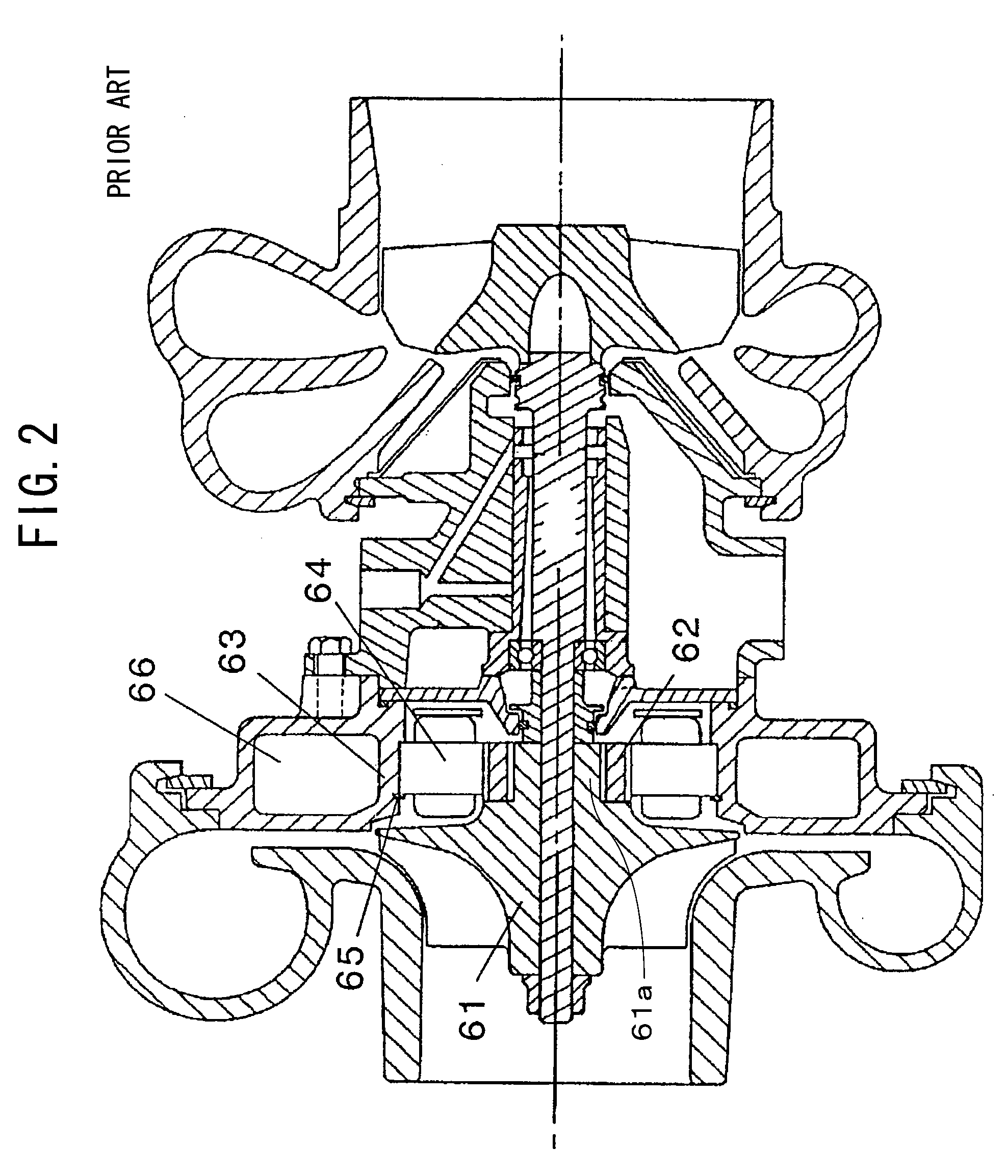
However, since a heat input from the compressor wheel 61 and the motor rotor 62 which are heated is large, it is impossible to efficiently cool a whole of t

Method used


Image

  • Motor-driven supercharger
  • Motor-driven supercharger
  • Motor-driven supercharger

Examples


Embodiment Construction

[0061]A description will be given below of a preferable embodiment in accordance with the present invention with reference to the accompanying drawings. In the drawings, the same reference numerals are attached to the common portions, and an overlapping description will be omitted.

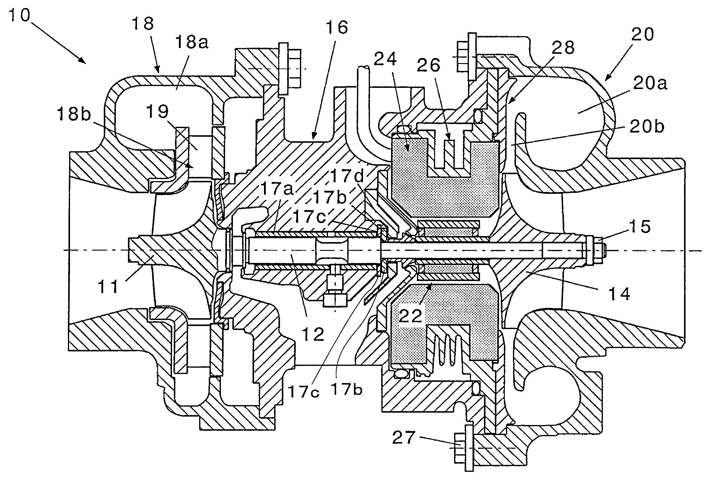
[0062]FIG. 4 is a schematic view of a whole of a motor-driven supercharger in accordance with the present invention. In this drawing, a motor-driven supercharger 10 in accordance with the present invention is provided with a turbine shaft 12, a compressor impeller 14, and a housing. The housing is constituted by a bearing housing 16, a turbine housing 18 and a compressor housing 20 in this embodiment.

[0063]The turbine shaft 12 has a turbine impeller 11 in one end (a left end in the drawing) of itself. In this embodiment, the turbine impeller 11 is integrally formed with the turbine shaft 12. However, the present invention is not limited to this, but may be structured such that the turbine impeller 11 is in...


PUM


Abstract

A motor stator (24) has a stator iron core (24a), a stator winding (24b), and a mold member (30) embedding them in an inner portion and having a high coefficient of thermal conductivity. The mold member (30) has a heat insulating layer (32) closely attached to an inner surface thereof surrounding a motor rotor (22) and to an outer surface thereof in an axial direction. Further, an outer sleeve (26) is provided so as to be closely attached to an outer peripheral surface of the mold member (30) and to an inner surface of a bearing housing (16). The outer sleeve (26) forms a liquid tight water cooling jacket (26b) between the outer sleeve and the bearing housing.

Description

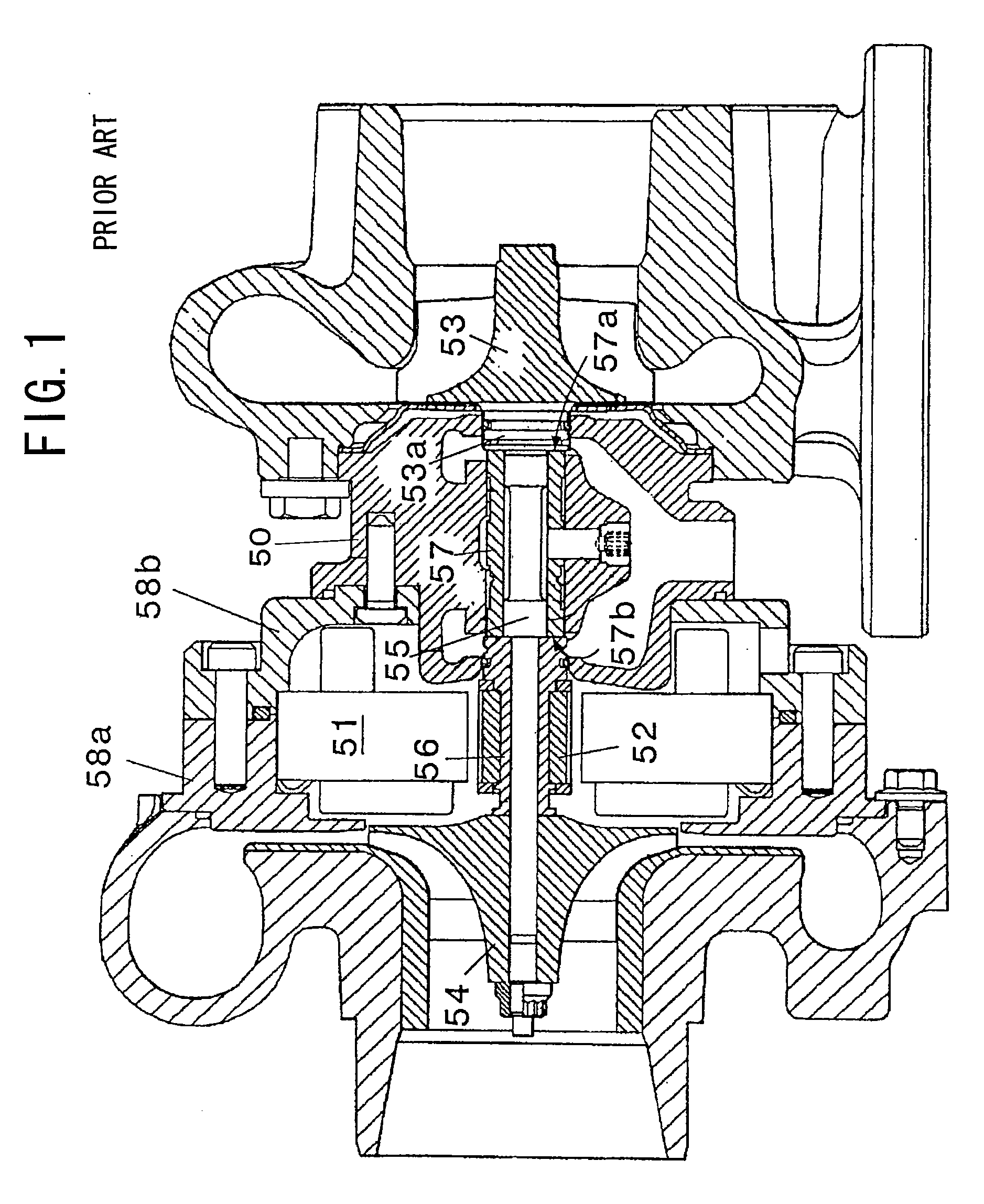
BACKGROUND OF THE INVENTION[0001]1. Field of the Invention[0002]The present invention relates to a motor-driven supercharger having a built-in electric motor.[0003]2. Description of the Related Art[0004]To supply an air having a density increased by a compressor to an engine is called supercharging, and an apparatus for performing a driving work of the compressor on the basis of an exhaust energy of an engine in the case of executing the supercharging is called as an exhaust-gas turbocharger.[0005]The exhaust-gas turbocharger is generally constituted by a compressor and a turbine which are arranged so as to sandwich a bearing unit therebetween. The compressor has a built-in compressor impeller, and the turbine has a built-in turbine impeller. The compressor impeller and the turbine impeller are coupled to each other by a connecting shaft (a shaft) supported by a bearing unit, and are structured such as to rotationally drive the turbine impeller on the basis of an exhaust gas of the ...

Claims


Application Information

Patent Timeline
IPC IPC(8): F04B35/04
CPCF01D25/12Y02T10/144F02B37/025F02B37/10F02B39/005F02B39/10F02C6/12F05D2220/40F05D2220/76F05D2260/2214F05D2300/5024H02K5/128H02K5/20H02K7/14H02K9/19H02K9/22F01D25/14Y02T10/12H02K9/227H02K5/203H02K9/223F02B39/00H02K3/44
Inventor SHIMIZU, MASAHIROSHIBUI, YASUYUKI
Owner IHI CORP
Why Eureka
Try Eureka