Flow field plate of a fuel cell with airflow guiding gaskets

a fuel cell and flow field technology, applied in the direction of cell components, final product manufacturing, sustainable manufacturing/processing, etc., can solve the problems of fuel cell not storing but only transforming energy, disadvantages of fuel cell, volume and weight, etc., to reduce the thickness, volume and weight of the flow field plate, simplify the production process, and reduce cost

Inactive Publication Date: 2010-09-30
TATUNG COMPANY
View PDF2 Cites 5 Cited by
  • Summary
  • Abstract
  • Description
  • Claims
  • Application Information

AI Technical Summary

Benefits of technology

[0009]This invention relates to a flow field plate of a fuel cell with airflow guiding gaskets, comprising a flat plate and an airflow guiding gasket. The flat plate includes a front side and a reaction area. The reaction area is provided on the front side and comprises therein a plurality of ribs and a plurality of grooves, in which the plurality of ribs and the plurality of grooves are disposed in parallel with each other and each of the plurality of ribs is interposed between two adjacent grooves. Each groove includes an inlet and an outlet. The flat plate is further provided with an inlet hole and an outlet hole outside the reaction area. In addition, an airflow guiding gasket is covered on the front side of the flat plate. The center of the air guiding gasket is hollowed to provide a hollowed region. The hollowed region corresponds to the reac

Problems solved by technology

However, the difference between a fuel cell and a battery is that the fuel cell does not store but only transforms energy.
It is disadvantageous to the fuel cell under the developing trend of pursuing reduction of the volume and weight.
Further, after the conventional flow field plate 8 is assembled, while membrane electrode assembli

Method used


Image

  • Flow field plate of a fuel cell with airflow guiding gaskets
  • Flow field plate of a fuel cell with airflow guiding gaskets
  • Flow field plate of a fuel cell with airflow guiding gaskets

Examples


Embodiment Construction

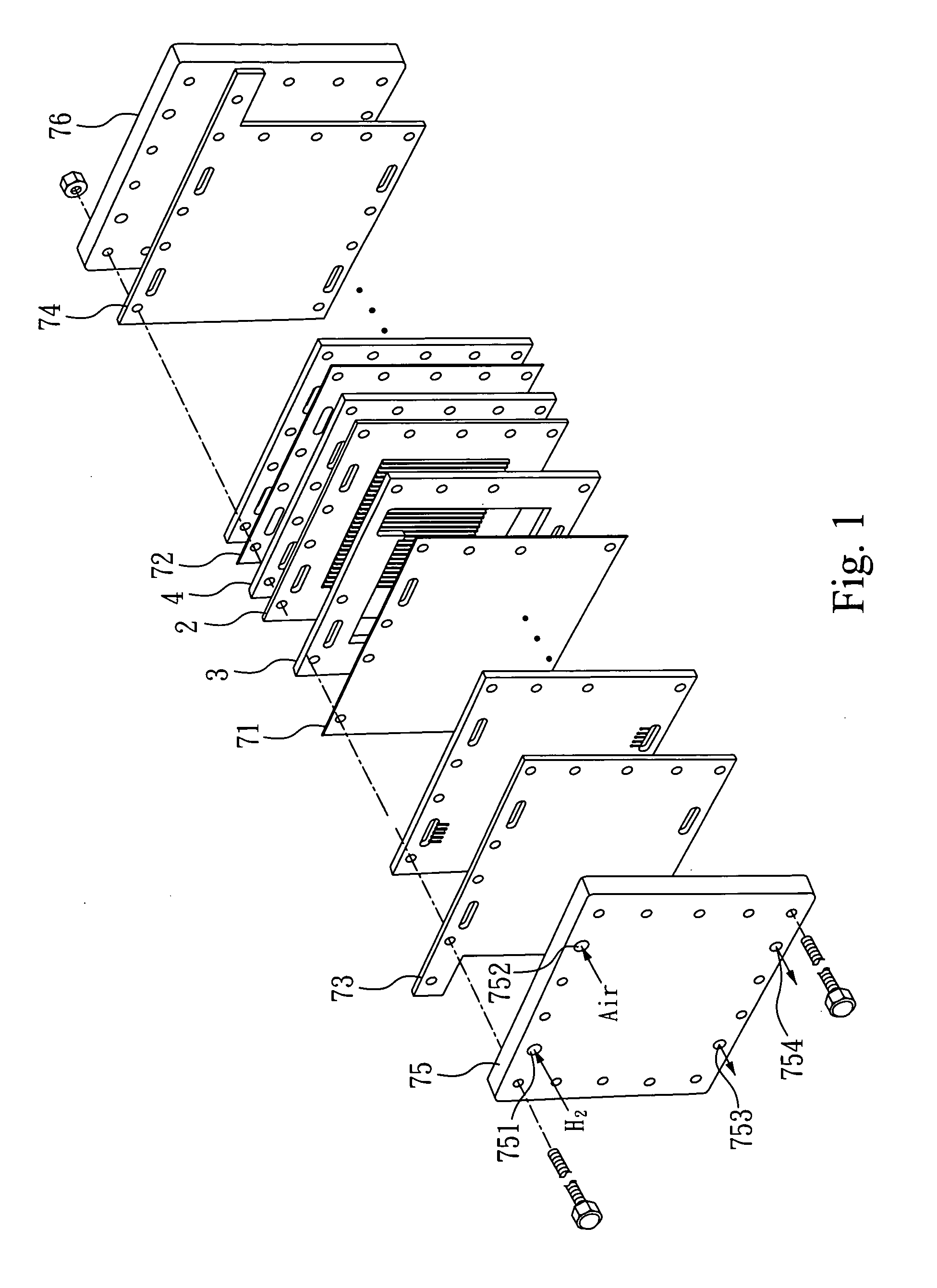
[0029]Please refer to FIG. 1. FIG. 1 is an exploded diagram of a whole fuel cell according to a preferred embodiment of the invention. The fuel cell of this invention mainly comprises a front plate 75, a back plate 76 and a plurality of flat plates 2. The plurality of flat plates 2 are disposed between the front plate 75 and the back plate 76. Further, a front collector plate 73 and a back collector plate 74 are respectively disposed between the inner side of the front plate 75 and the plurality of flat plates 2 and between the back plate 76 and the plurality of flat plates 2 for collecting current and transferring it to a load through an external circuit. Both sides of each of the flat plates 2 have an airflow guiding gasket 3 and an airflow guiding gasket 4, respectively. In addition, a membrane electrode assembly 71 and a membrane electrode assembly 72 are disposed at the other side of the airflow guiding gasket 3 and the other side of the airflow guiding gasket 4, respectively.

[...


PUM

PropertyMeasurementUnit
Flow rateaaaaaaaaaa
Volumeaaaaaaaaaa
Shapeaaaaaaaaaa

Abstract

The present invention relates to a flow field plate of a fuel cell with airflow guiding gaskets, comprising a flat plate and airflow guiding gaskets. Each side of the flat plate has a reaction area, which includes a plurality of ribs and a plurality of grooves. Two airflow guiding gasket are respectively covered on the two sides of the flat plate, and a central hollowed region of each airflow guiding gasket is corresponding to the reaction area. An inlet hole of the flat plate communicates with the hollowed region and each inlet of the grooves through an inlet trough of the airflow guiding gasket. An outlet hole of the flat plate communicates with the hollowed region and each outlet of the grooves through an outlet trough of the airflow guiding gasket. Thus, the present invention is capable of significantly reducing the volume of the fuel cell and lowering the weight.

Description

BACKGROUND OF THE INVENTION[0001]1. Field of the Invention[0002]This invention relates to a flow field plate of a fuel cell with airflow guiding gaskets, and particularly relates to a flow field plate of a fuel cell employing fluid fuel.[0003]2. Description of Related Art[0004]A fuel cell is a device capable of transforming the chemical energy stored in fuel and oxidation agent into electrical energy directly, and has advantages of high transforming efficiency, zero contamination, low noise, long life, and so on. Thus, the fuel cell can continue generating electrical power as long as the fuel and the oxidation agent are supplied to the fuel cell from outside continuously. According to the difference of electrolyte, the fuel cell can be divided into an alkaline fuel cell (AFC), a phosphoric acid fuel cell (PAFC), a melted carbonate fuel cell (MCFC), a solid oxidation fuel cell (SOFC), and a proton exchange membrane fuel cell (PEMFC).[0005]However, the difference between a fuel cell a...

Claims


Application Information

Patent Timeline
IPC IPC(8): H01M2/08
CPCH01M8/0206H01M8/0228H01M8/0254H01M8/026Y02E60/50H01M8/0276H01M8/0284H01M8/04089H01M2008/1095H01M8/0273Y02P70/50H01M8/0258H01M8/0263H01M8/0271H01M8/2483
Inventor CHANG, SUN-WEICHIH, CHUNG-WENYU, CHU-HSUEHLIN, YUNG-CHING
Owner TATUNG COMPANY
Why Eureka
Try Eureka