In-Situ System for Aerobic Heat Treatment of Biodegradable Organic Waste

a biodegradable organic waste and aerobic heat treatment technology, which is applied in the field of aerobic heat treatment can solve the problems of high cost of manufacturing the bioreactor when using stainless steel as its building material, system does not guarantee the uniform distribution of biodegradable organic waste, and disadvantages for use in mexico

Active Publication Date: 2010-09-30
INST TECHNOLOGICO & DE ESTUDIOS SUPERIORES DE MONTERREY
View PDF3 Cites 7 Cited by
  • Summary
  • Abstract
  • Description
  • Claims
  • Application Information

AI Technical Summary

Benefits of technology

[0009]The potential of the system which is the object of this invention lies in that it makes it possible to provide sustainable treatment of organic wastes, such as: sanitary wastes (feces, urine, and toilet paper); manure from catt

Problems solved by technology

Said patent application (JP 1998-300324A) presents disadvantages for use in Mexico, as well as in other countries, due to the climatic and economic reality of these countries.
Some of these disadvantages are described below:The cost of manufacturing the bioreactor is high when using stainless steel as its building material.
This makes the system inaccessible for the Mexican market; for this reason this patent application proposes innovations to the design of the decomposition chamber that allows a diversification of the building materials without putting the integrity of the chamber at risk when exposed to an elevated pH, salinity, or temperature, present therein.The mixing system does not guarantee uniform distribution of the biodegradable organic wastes throughout the bioreactor chamber, which affects the capacity for degradation of the system due to the fact that the opening used to introduce the organic wastes is eccentric.
As a result of an analysis of the mixture of the material introduced, this invention proposes a central opening to solve this problem.Heating of the decom

Method used


Image

  • In-Situ System for Aerobic Heat Treatment of Biodegradable Organic Waste
  • In-Situ System for Aerobic Heat Treatment of Biodegradable Organic Waste
  • In-Situ System for Aerobic Heat Treatment of Biodegradable Organic Waste

Examples


Embodiment Construction

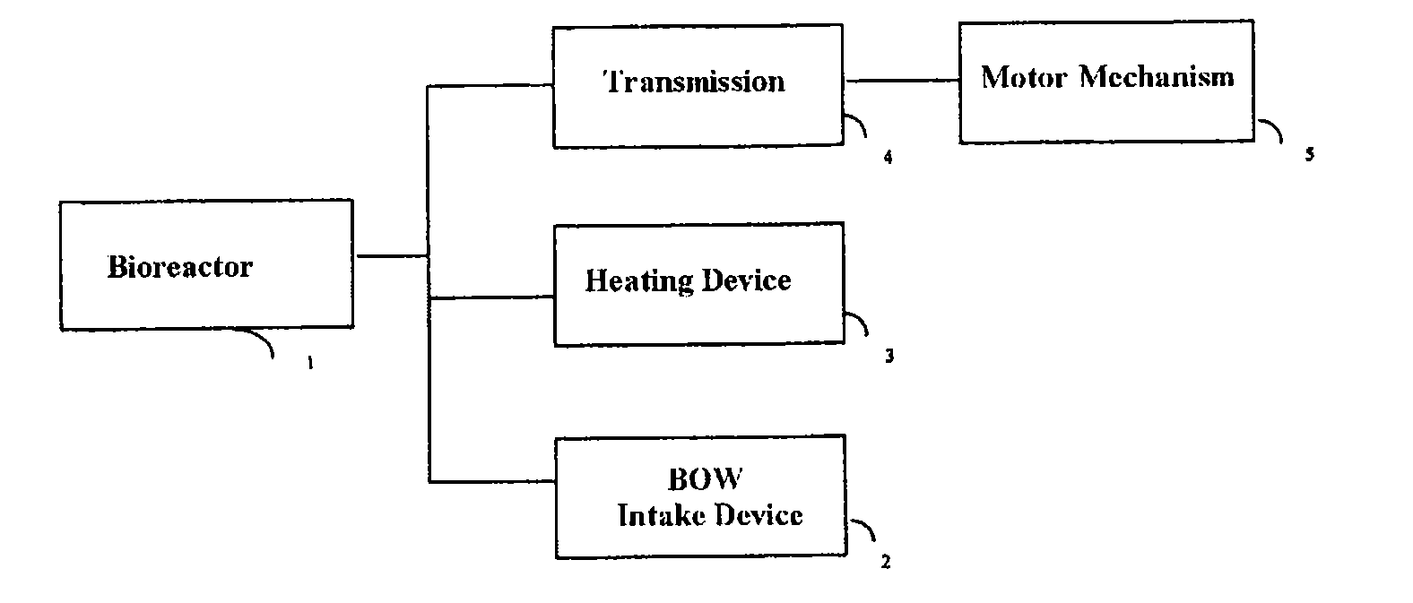
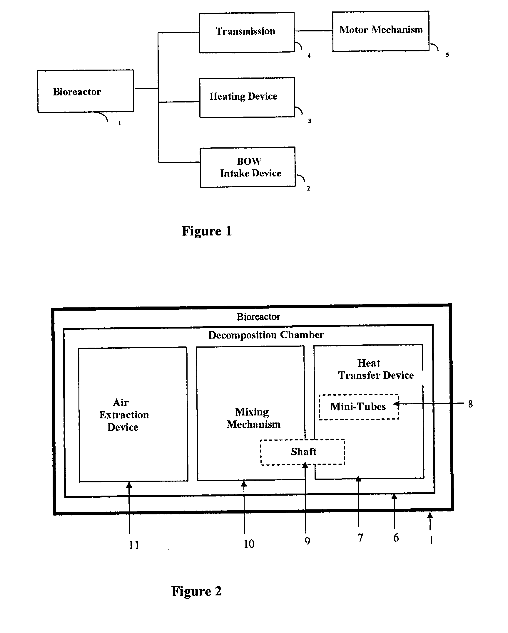
[0044]The in-situ system for aerobic heat treatment of biodegradable organic waste, which is the object of this invention, includes a bioreactor (1) that is connected to an input device for biodegradable organic waste (2), a heating device (3), and a transmission (4) which is powered by a motorized mechanism (5).

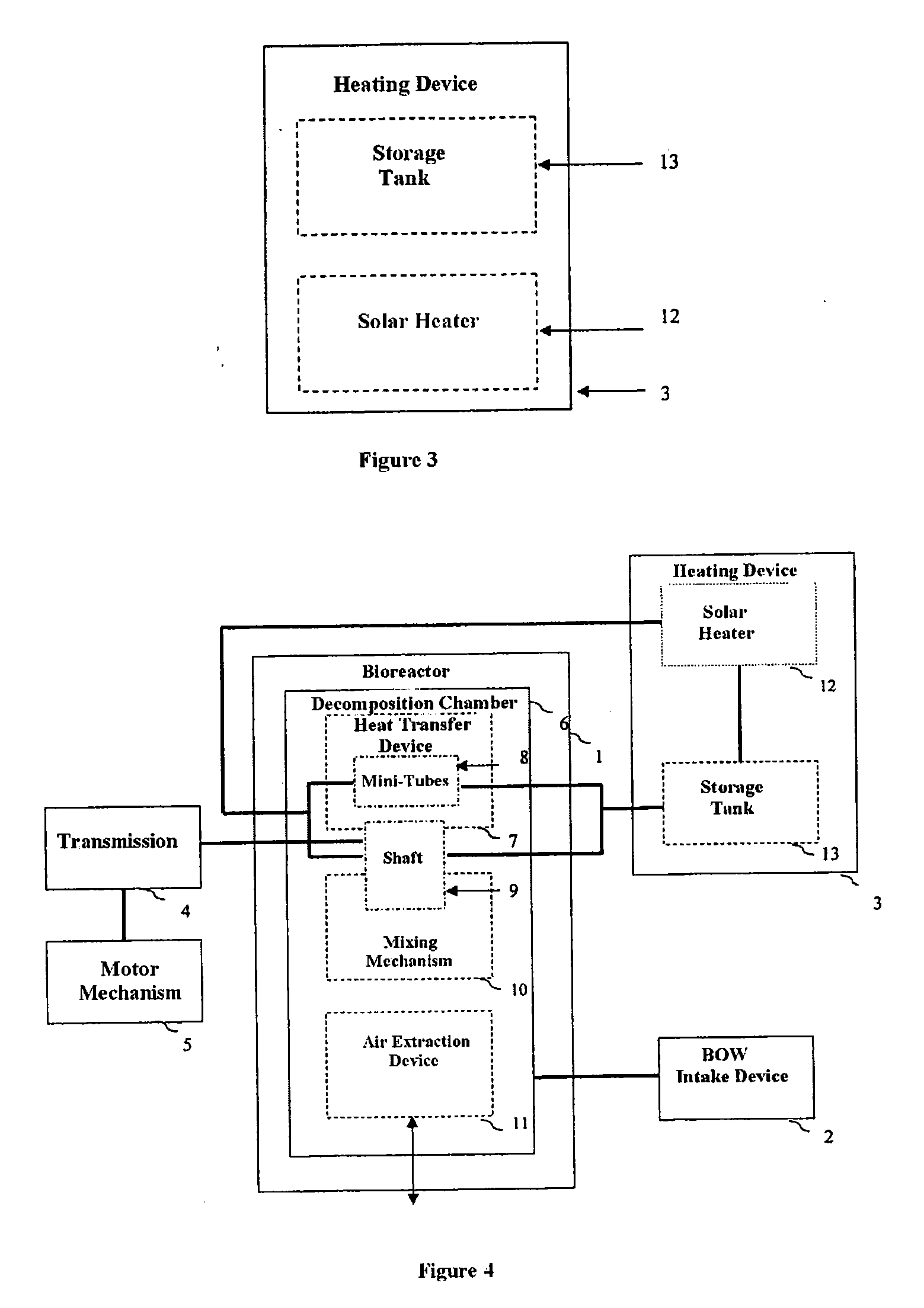
[0045]In FIG. 2, the bioreactor can be seen made up of a decomposition chamber (6) in parabolic shape that holds a sawdust matrix. The decomposition chamber (6), includes: a heat transfer device (7), that comprises a plurality of mini-tubes (8) and a shaft (9), through which a fluid is circulated that is heated via the solar heater (12) of the heating device (3), the heat of the hot liquid that passes through the inside of the shaft (9) and the inside of the plurality of mini-tubes (8) is transfer by conduction-convection to the sawdust matrix contained in the decomposition chamber (6), but the increase in temperature does not provide a condition sufficient to break down the...


PUM


Abstract

The proposed invention is an in-situ system for aerobic heat treatment of biodegradable organic waste, comprising a bioreactor made up of a dish-shaped decomposition chamber, said decomposition chamber being closed and having: a lid at the top, via which an air extraction device is connected, said device enabling fresh air to enter the decomposition chamber, and a preparation for a device for supplying the biodegradable organic waste; said decomposition chamber is also connected to a system of pipes which convey a hot fluid from the supply tank into a plurality of minitubes located longitudinally on the inner perimeter of the decomposition chamber, and into a shaft that forms part of the mixing mechanism; and, by means of a centrifugal pump, they convey the same fluid, but “cold”, from inside the minitubes and shaft to a solar collector, to heat it, before delivering it to a storage tank for subsequent recirculation.

Description

OBJECT OF THE INVENTION[0001]This invention describes an in-situ system for the aerobic heat treatment of biodegradable organic waste.BACKGROUND[0002]The patent application JP 1998-300324A describes a device for treating and decomposition of sanitary organic wastes (feces, urine, and toilet paper), kitchen wastes, and manure from ranching operations. Said patent application, includes a device built of stainless steel which includes a decomposition chamber that is partially filled with a sawdust matrix, a mixing mechanism powered by an electric motor, an electric heating system to raise the temperature in the decomposition chamber, and an air extraction system to create circulation therein, from the inside of the lavatory to the outside. The decomposition chamber is parabolic in form protected by a stainless steel cover that also serves as a base and support for the mixing mechanism and motor that powers it. The mixing mechanism is placed lengthwise in the chamber. It is made of stai...

Claims


Application Information

Patent Timeline
IPC IPC(8): C12M1/02
CPCB09B3/00B09B3/0083C05F17/0063C05F17/02C05F17/027C12M43/00F24J2/42F24J3/00C12M27/06C12M41/24C05F17/0276Y02W30/20Y02W10/37Y02P20/145Y02E10/40F24S90/00F24V99/00C05F17/60C05F17/979C05F17/986C05F17/90Y02W30/40B09B3/40
Inventor LOPEZ ZAVALA, MIGUEL ANGEL
Owner INST TECHNOLOGICO & DE ESTUDIOS SUPERIORES DE MONTERREY
Why Eureka
Try Eureka