Encoder

Active Publication Date: 2010-09-30
NOKIA TECHNOLOGLES OY
View PDF40 Cites 38 Cited by
  • Summary
  • Abstract
  • Description
  • Claims
  • Application Information

AI Technical Summary

Benefits of technology

[0013]This invention proceeds from the consideration that the currently proposed codecs lack fle

Problems solved by technology

Higher frequency region coding however does not produce an identical copy of the original high frequency region.
Specifically, the known higher frequenc

Method used


Image

  • Encoder
  • Encoder
  • Encoder

Examples


Embodiment Construction

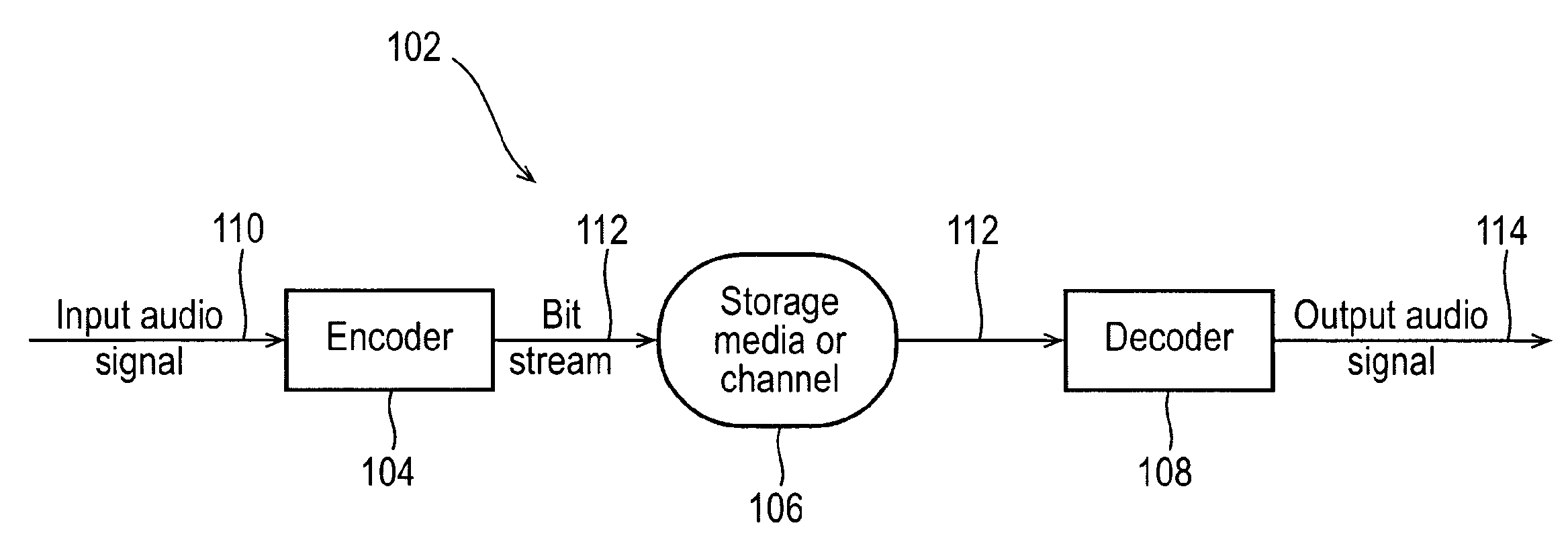
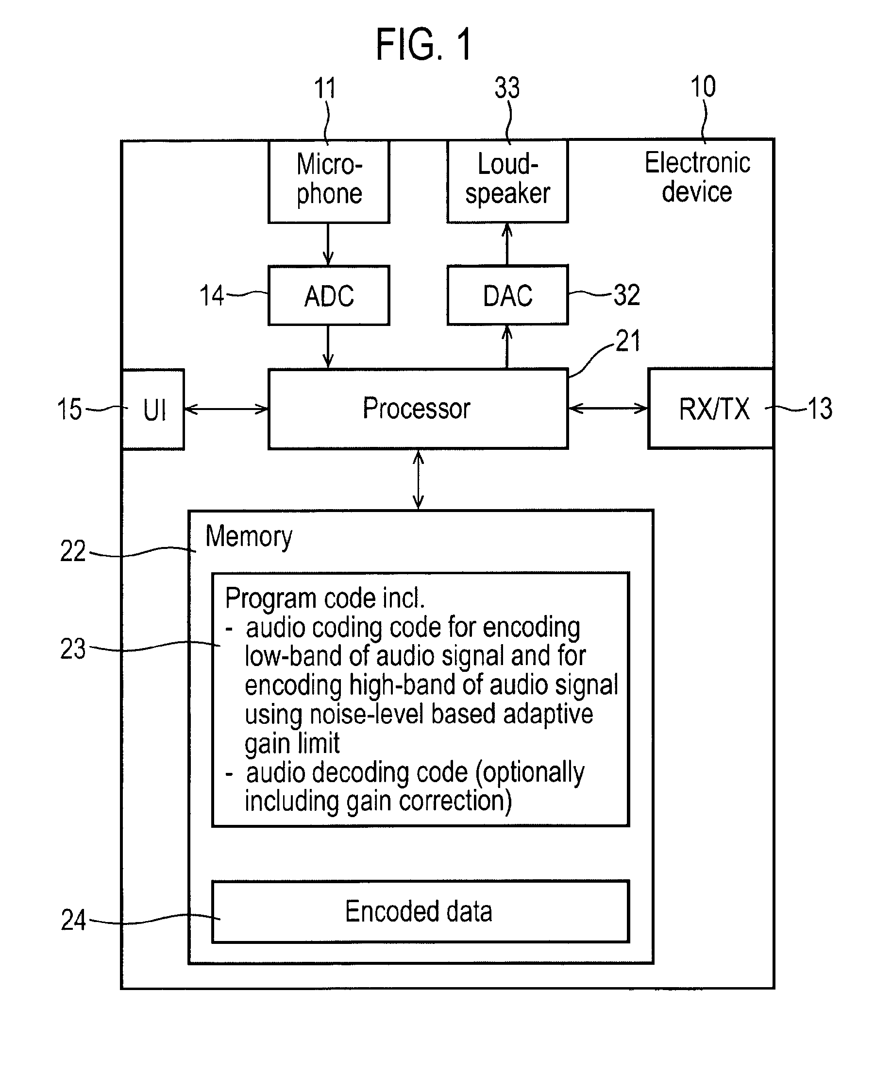
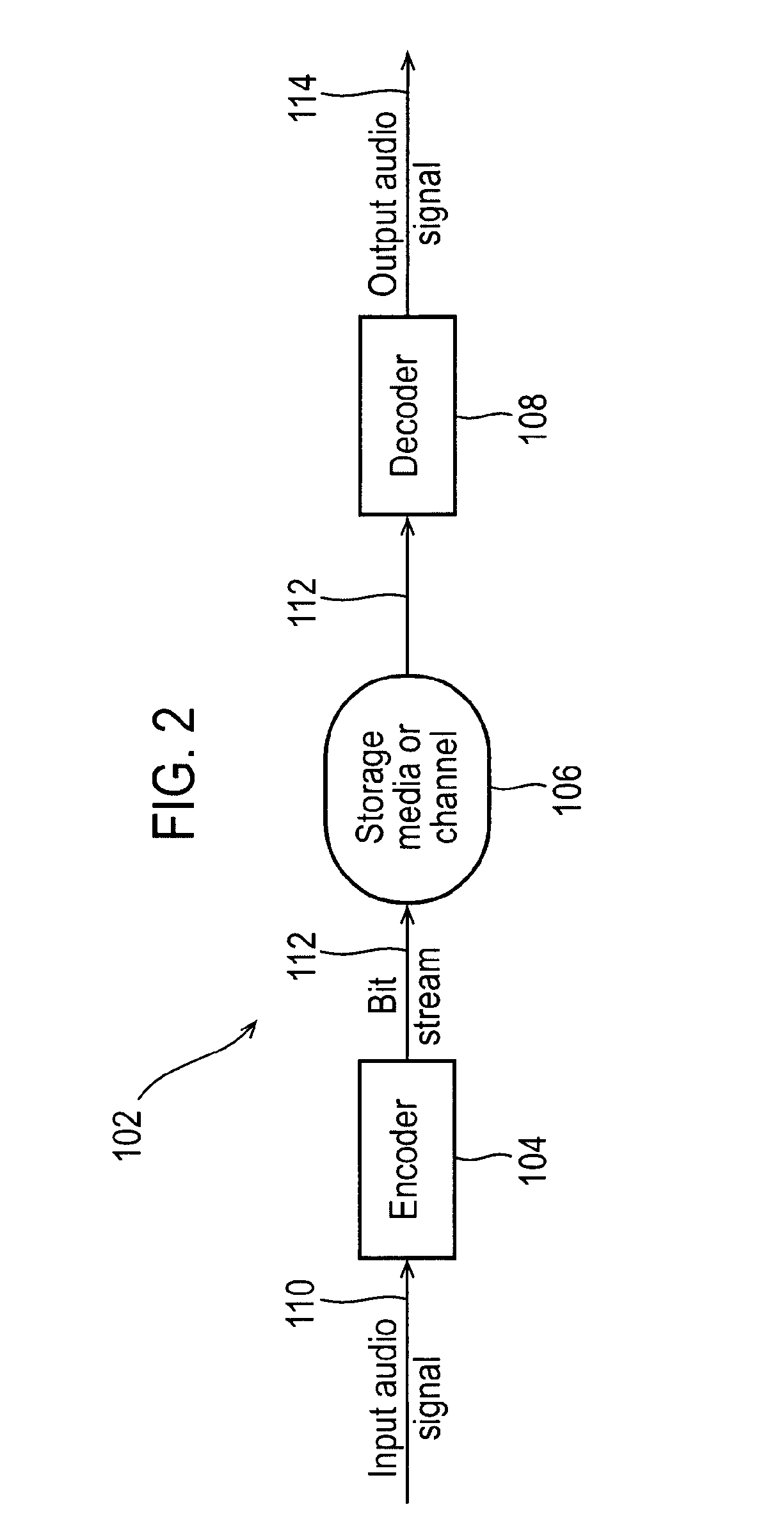
[0081]The following describes in more detail possible codec mechanisms for the provision of layered or scalable variable rate audio codecs. In this regard reference is first made to FIG. 1 which shows a schematic block diagram of an exemplary electronic device 10, which may incorporate a codec according to an embodiment of the invention.

[0082]The electronic device 10 may for example be a mobile terminal or user equipment of a wireless communication system.

[0083]The electronic device 10 comprises a microphone 11, which is linked via an analogue-to-digital converter (ADC) 14 to a processor 21. The processor 21 is further linked via a digital-to-analogue (DAC) converter 32 to loudspeakers 33.

[0084]The processor 21 is further linked to a transceiver (MTX) 13, to a user interface (UI) 15 and to a memory 22.

[0085]The processor 21 may be configured to execute various program codes. The implemented program codes comprise an audio encoding code for encoding a lower frequency band of an audio...


PUM


Abstract

An apparatus including at least one processor and at least one memory including computer program code the at least one memory and the computer program code configured to, with the at least one processor, cause the apparatus at least to select at least two single frequency components; generate an indicator, the indicator being configured to represent the at least two single frequency components and is configured to be dependent on the frequency separation between the two single frequency components.

Description

FIELD OF THE INVENTION[0001]The present invention relates to coding, and in particular, but not exclusively to speech or audio coding.BACKGROUND OF THE INVENTION[0002]Audio signals, like speech or music, are encoded for example for enabling an efficient transmission or storage of the audio signals.[0003]Audio encoders and decoders are used to represent audio based signals, such as music and background noise. These types of coders typically do not utilise a speech model for the coding process, rather they use processes for representing all types of audio signals, including speech.[0004]Speech encoders and decoders (codecs) are usually optimised for speech signals, and can operate at either a fixed or variable bit rate.[0005]An audio codec can also be configured to operate with varying bit rates. At lower bit rates, such an audio codec may work with speech signals at a coding rate equivalent to a pure speech codec. At higher bit rates, the audio codec may code any signal including mus...

Claims


Application Information

Patent Timeline
IPC IPC(8): G10L19/00G10L19/02G10L21/038
CPCG10L21/038G10L19/02
Inventor LAAKSONEN, LASSETAMMI, MIKKOVASILACHE, ADRIANARAMO, ANSSI
Owner NOKIA TECHNOLOGLES OY
Why Eureka
Try Eureka