Device for in situ extraction of a substance comprising hydrocarbons

a technology of hydrocarbon extraction and in situ extraction, which is applied in the direction of fluid removal, insulation, borehole/well accessories, etc., can solve the problems of reducing the thermal energy introduced into the storage site, reducing the operation reliability of the electric heater, and reducing the volume of the storage site. , to achieve the effect of increasing the electrical conductivity of the storage site, improving the reliability of the electric heater, and improving the reliability of the operation

Inactive Publication Date: 2010-10-07
SIEMENS AG
View PDF15 Cites 15 Cited by
  • Summary
  • Abstract
  • Description
  • Claims
  • Application Information

AI Technical Summary

Benefits of technology

[0019]The electrodes can be connected to one another electrically at their end regions remote from the power source by a connecting post. Thanks to such an electrical connection the operational reliability of the electric heater can be improved.
[0020]The injection pipeline and the production pipeline can have pipe sections running in the storage site essentially parallel to one another, oriented essentially horizontally. Seen in cross-section perpendicular to the injection and production pipeline, the electrodes of the electric heater are disposed on both sides of the injection and production pipeline. Thanks to an arrangement of the electrodes of the electric heater on both sides of the injection and production pipeline, the volume of the storage site, which extends in a horizontal direction between the injection and production pipelines, can in particular be heated by the electric heater. Particularly advantageously, a larger volume of the storage site can be extracted in this way. SAGD procedures known from the prior art achieve an extraction of between 40 and 60% of the bitumen present in the storage site. According to the embodiment described above, extraction levels of over 70% appear possible.
[0021]At least two of the electrodes of the electric heater can be formed by at least parts of the injection pipeline or the production pipeline. In that the electric heater is formed by at least parts of the injection or production pipeline, it is possible to cut down on additional material for the electric heater; another borehole is thus likewise dispensed with. Such a design of the electric heater is hence especially advantageous.
[0022]Hot steam can be applied to the inj

Problems solved by technology

The SAGD procedure currently practiced, as has been roughly outlined, exhibits various technical problems.
Firstly, hot steam can escape from the storage site via channels or porous rock strata present in the storage site, thereby reducing the thermal energy introduced into the storage site.
Excessive pressures in the storage site can result in soil distortions on the surface (blow-out), especially if the overburden is not very thick.
A further problem is “fingering” within the reservoir, whereby steam breakout (steam short-circuit) occurs generally at the start or end of the hor

Method used


Image

  • Device for in situ extraction of a substance comprising hydrocarbons
  • Device for in situ extraction of a substance comprising hydrocarbons
  • Device for in situ extraction of a substance comprising hydrocarbons

Examples


Embodiment Construction

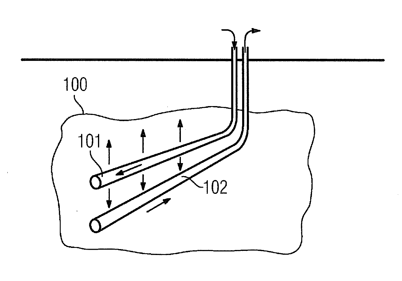
[0032]FIG. 1 shows a diagrammatic illustration of a device for in situ extraction of a substance comprising hydrocarbons from an underground storage site 100 while reducing the viscosity thereof. Such a device can for example be a device for extraction of bitumen from an oil sand deposit. An injection pipeline 101 runs from the earth's surface into the storage site 100. A production pipeline 102 leads out of the storage site 100 to the earth's surface. Devices are conceivable in which a plurality of injection pipelines 101 and a plurality of production pipelines 102 are used to convey the substance comprising hydrocarbons from the underground storage site 100. The storage site 100 can in particular be an oil sand deposit or an oil shale deposit, from which bitumen or other heavy oils can be extracted.

[0033]To be able to extract the substance comprising hydrocarbons from the storage site 100, the viscosity of the substance comprising hydrocarbons present in the storage site 100 must ...


PUM


Abstract

A device for in situ extraction of a substance including hydrocarbons while reducing the viscosity thereof from an underground storage site is provided. The device includes at least one production pipeline leading out of the storage site, and at least two electrodes which are inductively and resistively effective relative to at least parts of the storage site.

Description

CROSS REFERENCE TO RELATED APPLICATIONS[0001]This application is the US National Stage of International Application No. PCT / EP2008 / 060074 filed Jul. 31, 2008, and claims the benefit thereof. The International Application claims the benefits of German Application No. 10 2007 036 832.3 DE filed Aug. 3, 2007. All of the applications are incorporated by reference herein in their entirety.FIELD OF INVENTION[0002]The invention relates to a device for in situ extraction of a substance comprising hydrocarbons. The substance comprising hydrocarbons is conveyed from an underground storage site while reducing the viscosity thereof. The device comprises at least one production pipeline leading out of the storage site. Such devices for conveying substances comprising hydrocarbons are for example known from “Steam-Injection Strategy and Energetics of Steam-Assisted Gravity Drainage” by I. D. Gates, 2005, SPE International Thermal Operations and Heavy Oil Symposium, Calgary, Canada, Nov. 1-3, 2005...

Claims


Application Information

Patent Timeline
IPC IPC(8): E21B36/04E21B43/24
CPCE21B43/2401E21B43/305E21B43/2408
Inventor DIEHL, DIRKWACKER, BERND
Owner SIEMENS AG
Why Eureka
Try Eureka