
Magnetic resonance method and apparatus to determine k-space positions for modeling radio-frequency pulses

a radiofrequency pulse and magnetic resonance technology, applied in the field of magnetic resonance methods and apparatus to determine kspace positions for modeling radiofrequency pulses, can solve the spatial variations of mr signal strength and image contrast, the cost of providing independent transmission channels, and the inability to achieve the degree of homogeneity of rf field that can be achieved with this method, so as to achieve a simple determination of k-space positions. the effect of fas

Inactive Publication Date: 2010-10-07
SIEMENS HEALTHCARE GMBH
View PDF8 Cites 13 Cited by
  • Summary
  • Abstract
  • Description
  • Claims
  • Application Information

AI Technical Summary

Benefits of technology

[0012]An object of the present invention to provide a method, a magnetic resonance apparatus and a computer-readable medium encoded with programming instructions that enable a fast a simple determination of k-space positions for modeling of RF pulses.

Problems solved by technology

This leads to spatial variations of the MR signal strength and the image contrast (i.e. to unwanted, artificial shadowings in the MR image), particularly in whole-body imaging (breast, abdomen, pelvis), but also in head acquisitions (in particular at higher field strengths).
However, the degree to homogeneity of the RF field that can be achieved with this method is limited.
Providing independent transmission channels is expensive.
In principle, the spatial homogeneity of an RF excitation or refocusing that can be achieved in this manner is not limited, but the RF pulses that are required for this require disadvantageously long pulse times. However, the pulse times in the spatially selective excitation can in principle be shortened again by a parallel transmission with multiple transmission coils.
This method is limited, however, to only the transmission with one channel.
Due to its high complexity, this method requires significant computing time.
Moreover, it is not taken into account how robust an RF pulse optimized in this manner is against measurement errors in the calculation of detailed parameters (in particular those known as “B1 maps” that represent an achieved transversal magnetization) for the determination of a desired excitation pattern and against system imperfections.
Moreover, the complex mathematical solutions are physically less transparent.

Method used


Image

  • Magnetic resonance method and apparatus to determine k-space positions for modeling radio-frequency pulses
  • Magnetic resonance method and apparatus to determine k-space positions for modeling radio-frequency pulses
  • Magnetic resonance method and apparatus to determine k-space positions for modeling radio-frequency pulses

Examples


Embodiment Construction

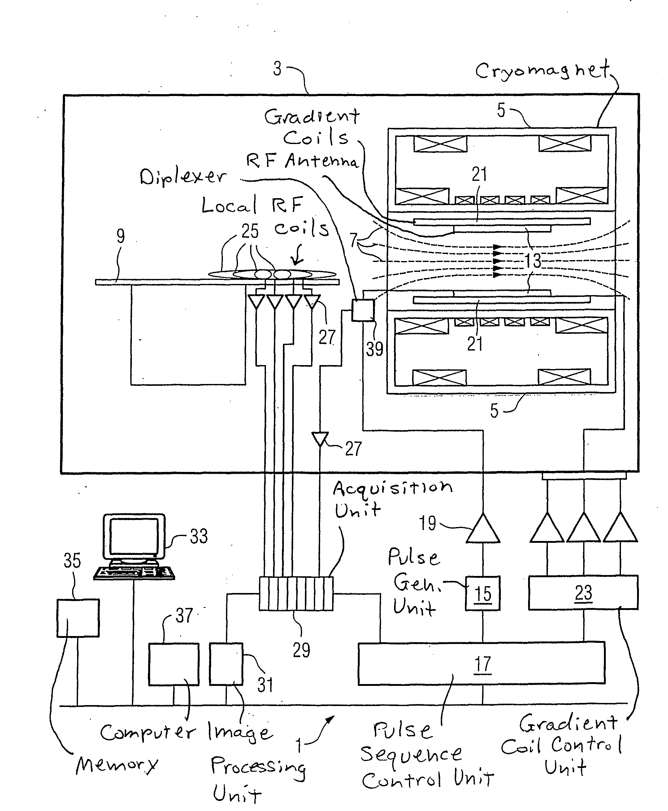
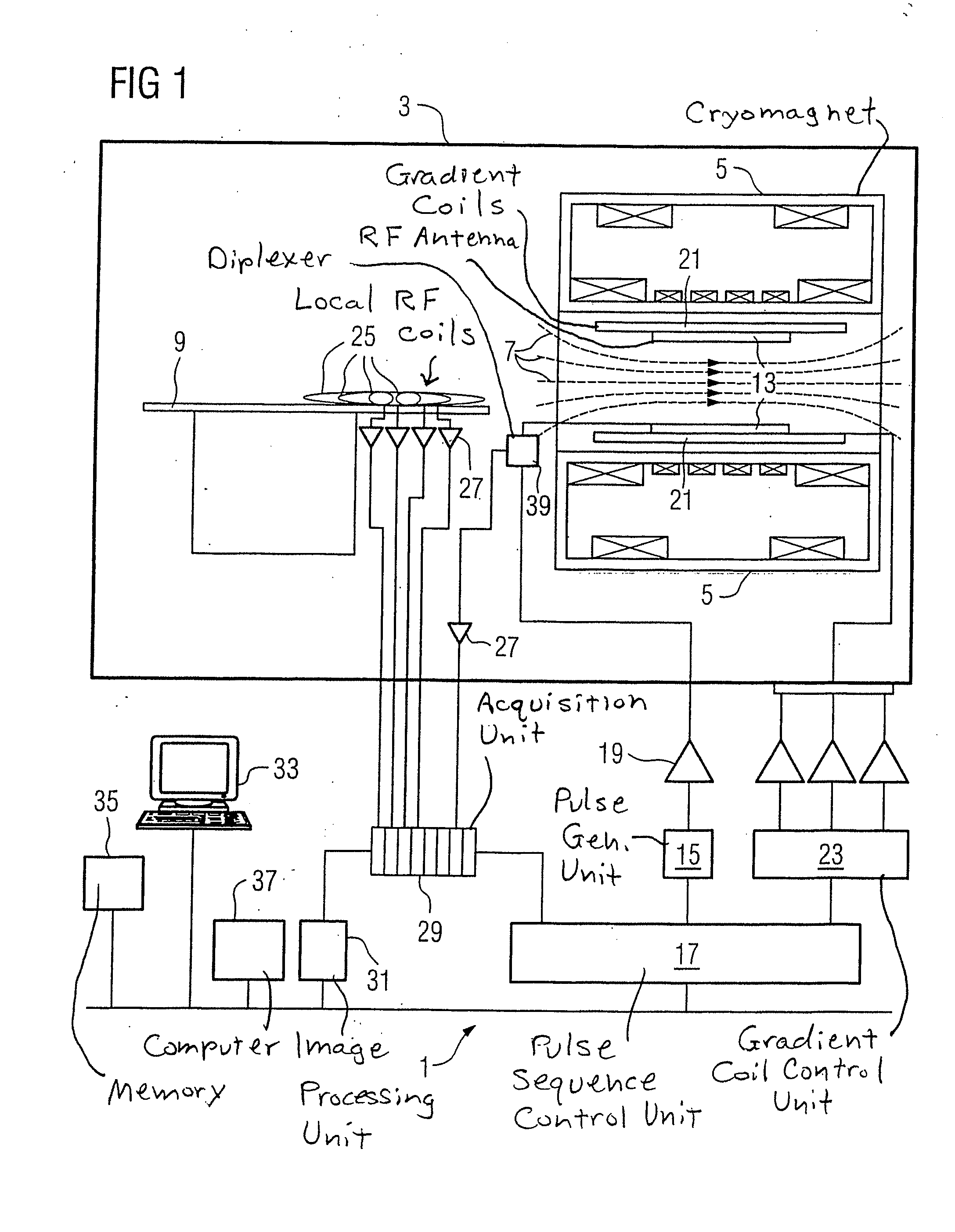
[0028]FIG. 1 schematically shows the design of the basic component of a magnetic resonance apparatus 1 with its essential components. In order to examine a body by means of magnetic resonance imaging, different magnetic fields, matched to one another as precisely as possible with regard to their temporal and spatial characteristics, are radiated into the body.

[0029]A strong magnet (typically a cryomagnet 5 with a tunnel-shaped opening) arranged in a radio-frequency-shielded measurement chamber 3 generates a static, strong basic magnetic field 7 that typically amounts to 0.2 Tesla to 7 Tesla or more. An examination subject (for example a patient, not shown) to be examined is supported on a patient bed 9 and is positioned in the homogeneous region of the basic magnetic field 7.

[0030]The excitation of the nuclear spins in the examination subject ensues by magnetic radio-frequency pulses (RF pulses) that are radiated by at least one radio-frequency transmission coil (for example a radio...


PUM


Abstract

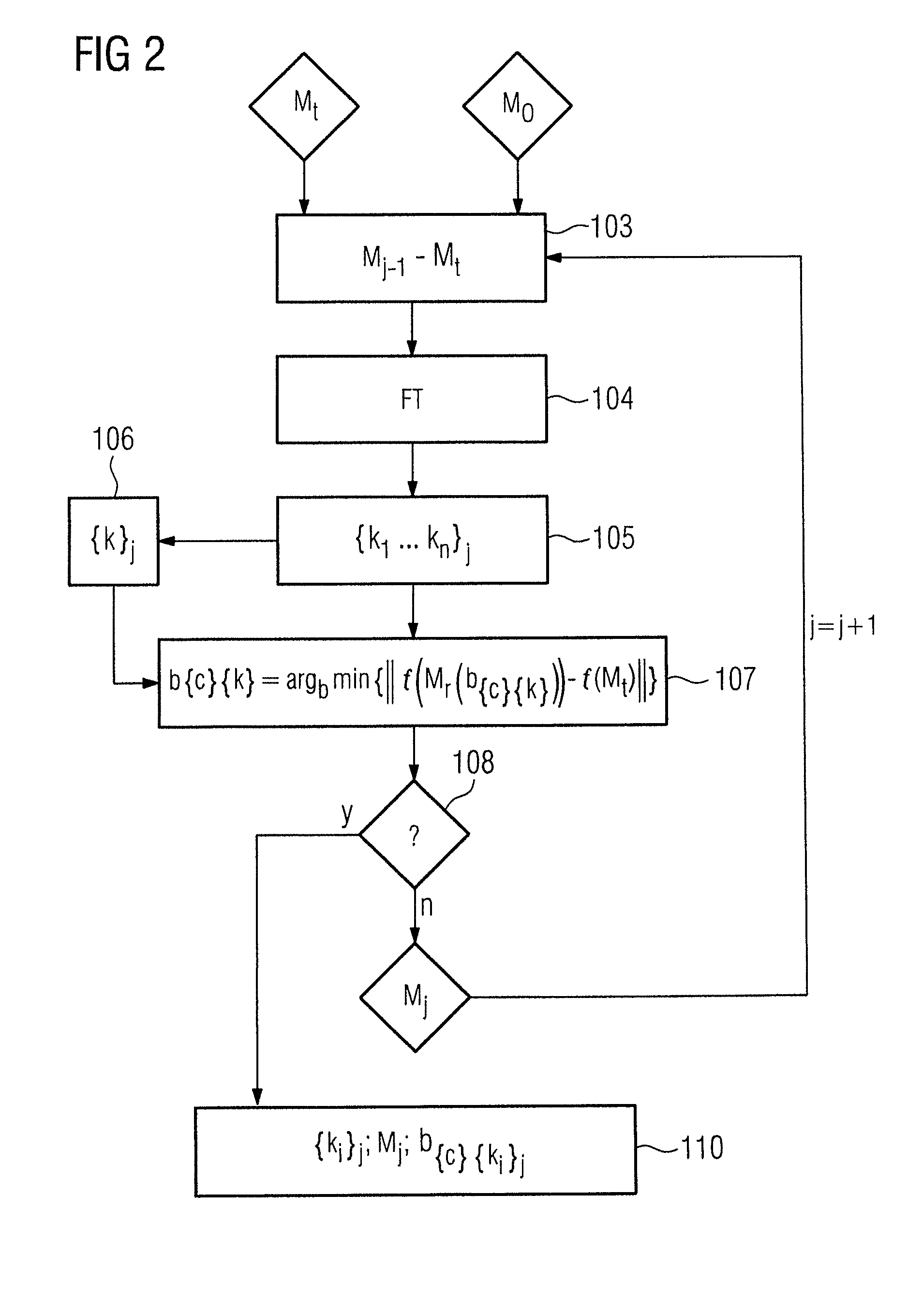
In a method magnetic resonance apparatus for the determination of k-space positions for modeling of RF pulses for magnetic resonance excitations, the following steps are implemented:(a) select a target magnetization,(b) select a first achievable magnetization as a current achievable magnetization,(c) determine a deviation of the current achievable magnetization from the target magnetization,(d) determine the spectrum of the deviation in k-space as a current spectrum,(e) localize at least one maximum in the current spectrum,(f) store the k-space positions of the localized maxima in a set of previously determined k-space positions,(g) determine current pulse coefficients with which an optimal, current magnetization can be achieved using at least one k-space position from the set of previously determined k-space positions, and(h) repeat (c) through (g) until a predeterminable termination criterion is satisfied (however at least once), wherein in each repetition at least one k-space position is used in the determination of current pulse coefficients that was used in none of the preceding determinations of current pulse coefficients.

Description

BACKGROUND OF THE INVENTION[0001]1. Field of the Invention[0002]The present invention concerns a method to determine k-space positions for modeling radio-frequency (RF) pulses for magnetic resonance excitations, as well as a magnetic resonance apparatus and a computer-readable storage to implement the method.[0003]2. Description of the Prior Art[0004]One source of unwanted artifacts in magnetic resonance exposures (MR exposures) is spatial variations in the distribution of an applied radio-frequency field (RF field) in the examination volume (also called B1 or RF field inhomogeneities). These RF field inhomogeneities intensify as the strength of the basic magnetic field that is used is increased. Factors that lead to such RF field inhomogeneities are, for example, the local dielectric properties and the local conductivity properties in an examination subject that can shorten the RF wavelengths or, respectively, attenuate the RF amplitude. For example, spatially inhomogeneous RF fiel...

Claims


Application Information

Patent Timeline
IPC IPC(8): G01R33/48
CPCG01R33/5659G01R33/4833
Inventor FAUTZ, HANS-PETER
Owner SIEMENS HEALTHCARE GMBH
Learn More