Method for manufacturing gas supply structure in electrostatic chuck apparatus, gas supply structure in electrostatic chuck apparatus, and electrostatic chuck apparatus

a technology of electrostatic chuck and gas supply structure, which is applied in the direction of electrostatic holding devices, machines/engines, transportation and packaging, etc., can solve the problems of generating suspended matter and becoming a source of contamination, and achieve the effect of preventing non-uniform jet amount of cooling gas and contamination, and excelling durability

Active Publication Date: 2010-10-07
CREATIVE TECH CORP
View PDF3 Cites 10 Cited by
  • Summary
  • Abstract
  • Description
  • Claims
  • Application Information

AI Technical Summary

Benefits of technology

[0020]According to the method of manufacturing the gas supply structure of the present invention, it is possible to eliminate a possibility of occurrence of deposition and adhesion of a part of thermal sprayed material in the gas supply path of the metal base when the lower insulating layer is formed by thermal spraying. Therefore, it is possible to eliminate the conventional problem that a part of deposits suspends together with the cooling gas in the gas supply path so as to cause unevenness of gas flow rate to be supplied to the substrate side, or to be jetted to the substrate side so as to cause contamination. The method according to the present in

Problems solved by technology

This is because a material of the clamp itself (aluminum material in many cases) is exposed to plasma during the treatment to be spattered therefrom, or ion irradiation in the ion implantation treatment causes the clamp to be spattered, which lead to generation of suspended matter.
In addition, t

Method used


Image

  • Method for manufacturing gas supply structure in electrostatic chuck apparatus, gas supply structure in electrostatic chuck apparatus, and electrostatic chuck apparatus
  • Method for manufacturing gas supply structure in electrostatic chuck apparatus, gas supply structure in electrostatic chuck apparatus, and electrostatic chuck apparatus
  • Method for manufacturing gas supply structure in electrostatic chuck apparatus, gas supply structure in electrostatic chuck apparatus, and electrostatic chuck apparatus

Examples


example 1

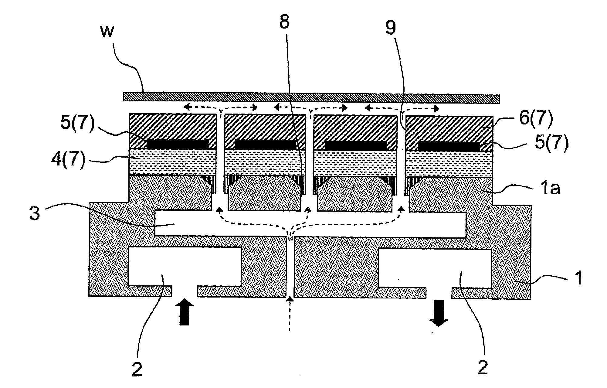
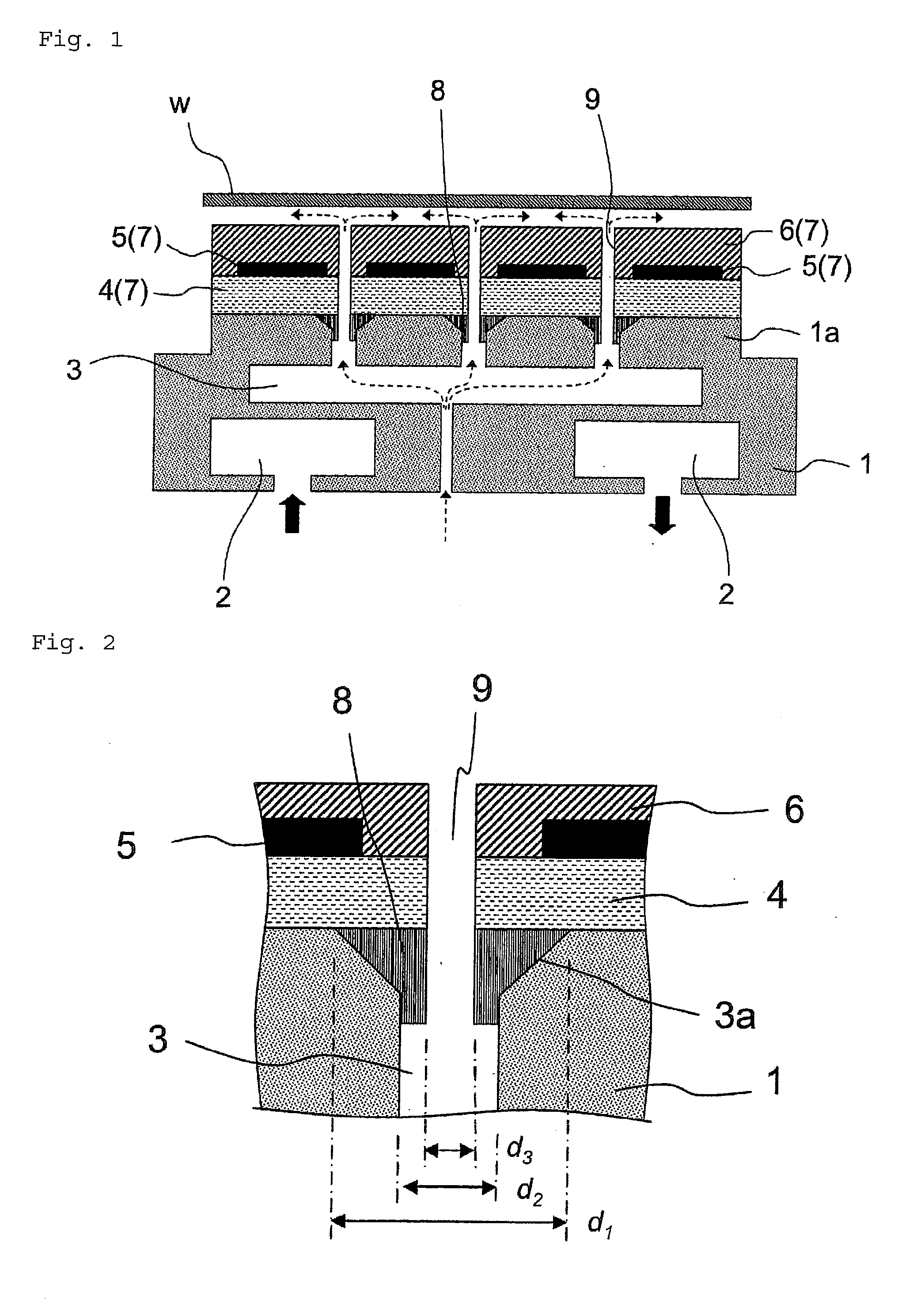
[0029]FIG. 1 is a cross sectional explanatory diagram of an electrostatic chuck apparatus having a gas supply structure according to the present invention, and FIG. 2 is a cross sectional explanatory diagram of the gas supply structure enlarged in part. Here, an example of a metal base 1 made of aluminum is mainly described, which is suitable for attracting a silicon wafer having a diameter of 300 mm. An upper surface side of the metal base 1 has a placement table 1a having a diameter of 196 mm. In addition, liquid conduit 2 are formed inside the metal base 1 so as to allow water supplied from the lower surface side to circulate and flow out from the lower surface side again. Further, a gas supply path 3 is formed for supplying a cooling gas supplied from the lower surface side of the metal base 1 (as illustrated by broken lines with arrows in FIG. 2) to the substrate w attracted to the electrostatic chuck 7 that is formed later. The gas supply path 3 is described in more detail as ...

example 2

[0032]Next, an example of a case of reproducing a gas supply structure of a used electrostatic chuck apparatus is described.

[0033]First, the upper insulating layer 6, the attracting electrode 5, and the lower insulating layer 4 were removed from a used electrostatic chuck apparatus by machine grinding with manual work in part. In this case, the process was performed so that the lower insulating layer 4 remained in part on the surface, and further a sandblast process was performed so that the metal base 1 was removed by the thickness in a range from 0.05 to 0.5 mm. Thus, the metal base surface was exposed so that flatness of the placement table 1a of the metal base 1 was reduced to 30 μm or smaller. Next, the gas supply path outlet 3a of the metal base 1 was chamfered in a range from C0.2 to 2 mm so as to prepare the metal base 1 for reproduction.

[0034]After removing burrs of the above-described metal base 1 and cleaning the same with organic solvent, all the gas supply path outlets ...


PUM

PropertyMeasurementUnit
Diameteraaaaaaaaaa

Abstract

Provided is a method of manufacturing a gas supply structure for use in an electrostatic chuck apparatus having an electrostatic chuck on the upper surface side of a metal base (1), the gas supply structure being capable of eliminating contamination due to nonuniform cooling gas jetting quantities and deposition of a thermally spraying material and the like. The method of manufacturing the gas supply structure for supplying a cooling gas supplied from the lower surface side of the metal base (1) to the back surface of a substrate (W) attracted to an upper insulating layer (6) side, through a gas supply path (3) provided on the metal base (1), the method including: prior to a step of forming a lower insulating layer (4) by thermally spraying a ceramic powder on the upper surface side of the metal base (1), a step of forming an attracting electrode (5), and a step of forming the upper insulating layer (6), a step of blocking a gas supply path outlet (3a) on the upper surface side of the metal base (1) with an adhesive (8), the adhesive containing a filler made of the same material as that of the ceramic powder that is used for forming the lower insulating layer (4); and a step of opening a hole toward the gas supply path outlet (3a) of the metal base (1) after forming the upper insulating layer (6), to thereby form a through hole (9) reaching the gas supply path (3).

Description

TECHNICAL FIELD[0001]The present invention relates to a method of manufacturing a gas supply structure applied to an electrostatic chuck apparatus, a gas supply structure applied to an electrostatic chuck apparatus, and an electrostatic chuck apparatus. Specifically, the present invention relates to a gas supply structure applied to an electrostatic chuck apparatus, for cooling, with cooling gas, a substrate attracted by an electrostatic chuck.BACKGROUND ART[0002]As to a plasma treatment apparatus, an electron lithography apparatus, an ion implantation apparatus, and the like, which are used in a manufacturing process of a semiconductor device, and an ion doping apparatus and the like, which are used for manufacturing a liquid crystal panel, it is required to securely hold a semiconductor wafer, a glass substrate, or the like, which is an object to be treated, without causing damage thereto. In particular, contamination of the semiconductor wafer, the glass substrate, or the like, t...

Claims


Application Information

Patent Timeline
IPC IPC(8): H02N13/00H01R43/00
CPCH01L21/67109H01L21/6831H02N13/00Y10T29/49126Y10T29/49002Y10T29/49117Y10T29/4913Y10T137/8593
Inventor MIYASHITA, KINYAWATANABE, YOSHIHIRO
Owner CREATIVE TECH CORP
Why Eureka
Try Eureka