Communication device

a communication device and receiver technology, applied in the field of communication devices, can solve the problems that the thermal noise in the receiver is not considered herein for simplicity, and achieve the effects of high accuracy, easy performance of site diversity, and high accuracy

Active Publication Date: 2010-10-07
SHARP KK
View PDF17 Cites 56 Cited by
  • Summary
  • Abstract
  • Description
  • Claims
  • Application Information

AI Technical Summary

Benefits of technology

[0019]With radio communication techniques according to the present invention, symbols transmitted simultaneously from a plurality of antennas are given different phase rotation for the antennas, whereby a receiving side separates and calculates delay profiles of the signals transmitted from the antennas. That is, by transmitting preambles to which different phase rotation has been applied for a plurality of antennas or cells, a receiving side separates a delay profile of a signal coming from each antenna or each cell to identify a transmitting antenna or a transmitting base station and to estimate a channel response. If the number of delay profiles to be separated is large, different preamble patterns are used together, realizing highly accurate separation of a delay profile.
[0022]The use of the present invention enables to separate and identify OFDM signals transmitted simultaneously from a plurality of base stations and estimate a channel response of a desired signal with high accuracy. It also enables to detect a signal of a base station to connect to at the start of communication and at handover with high accuracy. It further makes performing site diversity easy by transmitting identical data from a plurality of adjacent base stations, improving receiving features of a terminal being positioned around a cell boundary. If each base station comprises a plurality of transmitting antennas, a sequence of signal specific to the base station as a signal to estimate a channel response is used. Then, by giving phase rotation differing among transmitting antennas to the signal to estimate a channel response and by transmitting the signal, a channel response of a desired signal can be estimated with high accuracy even in the environment in which many signals are to be separated.
[0023]Furthermore, the use of the present invention enables to select an appropriate transmitting antenna or the number of transmitting antennas depending on the status of a channel response when a transmitting device comprising a plurality of transmitting antennas conducts selective transmit diversity transmission or MIMO transmission.

Problems solved by technology

However, thermal noise in a receiver is not considered herein for simplicity.

Method used


Image

  • Communication device
  • Communication device
  • Communication device

Examples


first embodiment

[0047]First, a radio communication technique according to the present invention will be described with reference to the drawings.

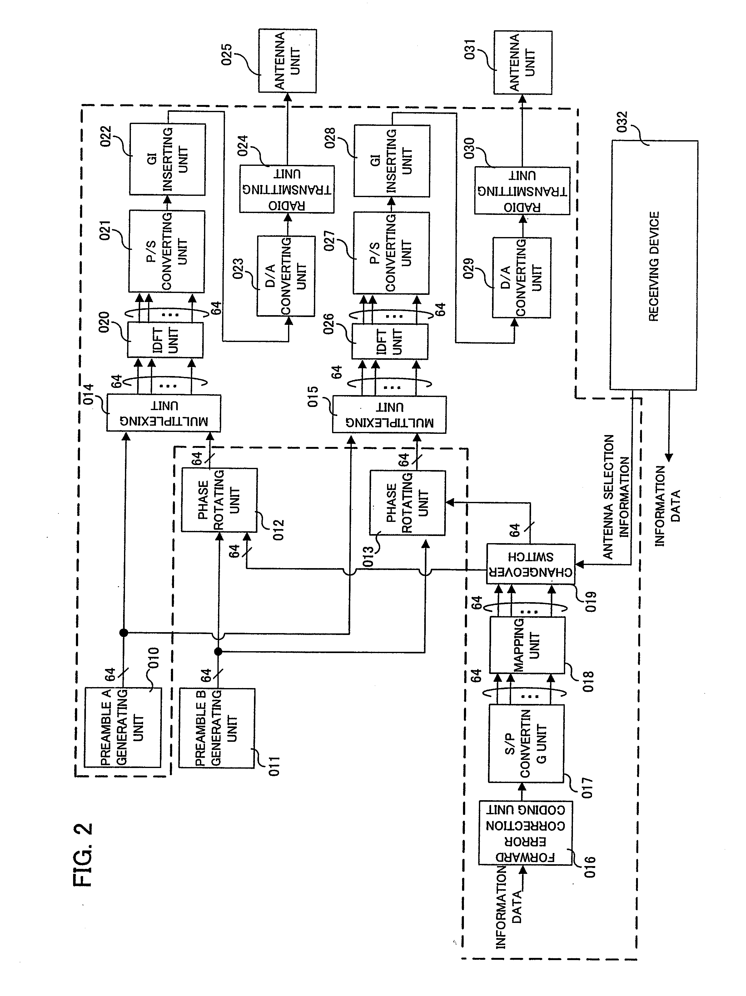
[0048]The radio communication technique according to the first embodiment of the present invention is directed to downlink transmission, in which a transmitting (base station) side comprises a plurality of antennas, and relates to an antenna selection manner for performing transmitting antenna selection diversity. According to this embodiment, a plurality of antennas simultaneously transmit OFDM signals, and a receiving side separates the signals transmitted from the respective antennas and estimates which antenna has transmitted a received signal having the highest power.

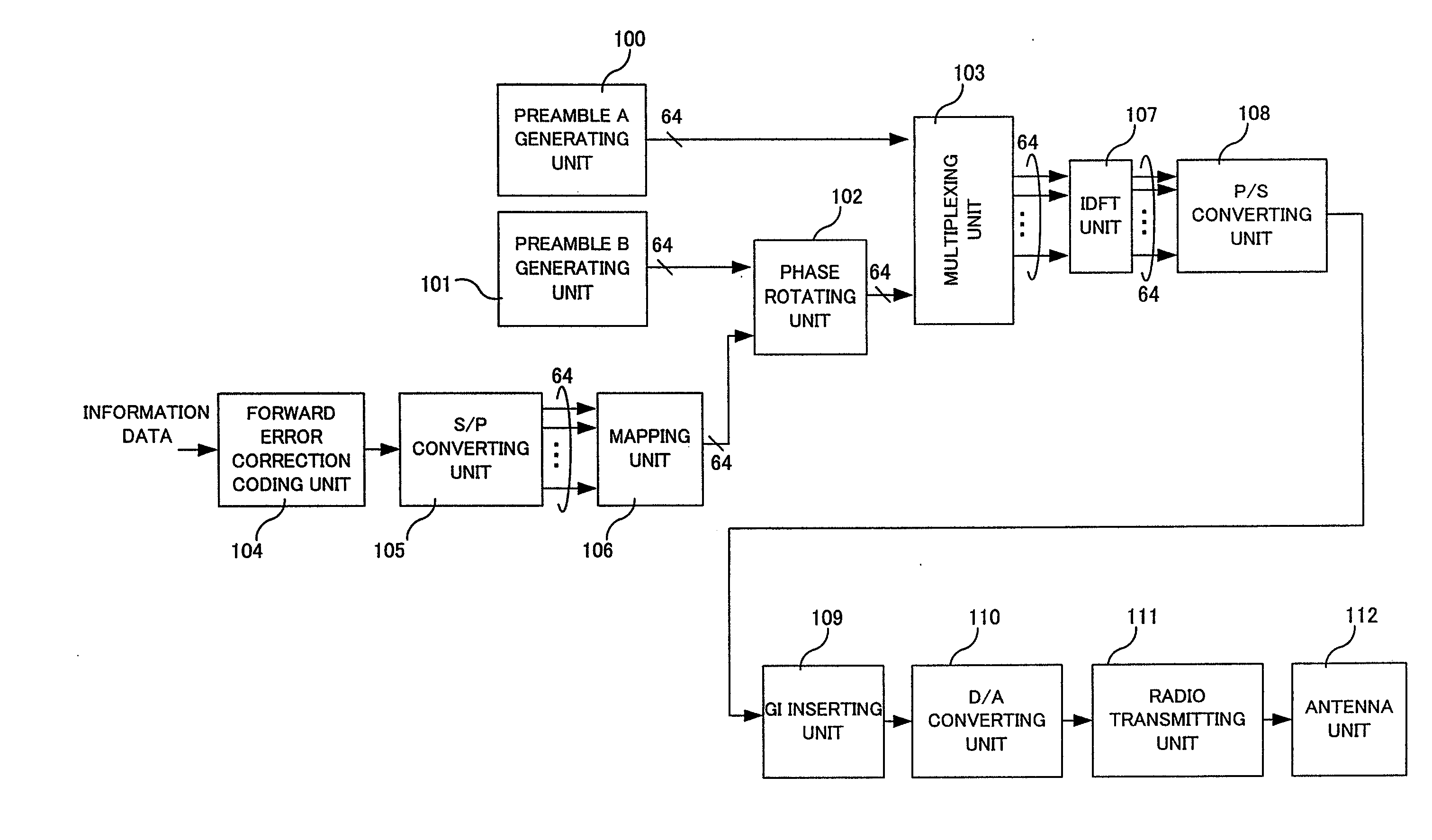
[0049]FIG. 2 is a diagram showing a configuration example of a transmitting device of a base station among radio communication devices according to the first embodiment of the present invention. However, an example is described in which the transmitting device comprises two transmitting a...

second embodiment

[0064]First, a configuration example of a transmitting device according to the present invention is shown in FIG. 9. FIG. 9 is a diagram showing a configuration example of a transmitting device including three transmitting antennas. As shown in FIG. 9, the transmitting device according to this embodiment includes a preamble A generating unit 200, a preamble B generating unit 201, phase rotating units 202, 203 and 204, multiplexing units 205, 206 and 207, a data modulating unit 208, a changeover switch 209, IDFT units 210, 216 and 222, P / S converting units 211, 217 and 223, GI inserting units 212, 218 and 224, D / A converting units 213, 219 and 225, radio transmitting units 214, 220 and 226, and antenna units 215, 221 and 227. As shown in FIG. 9, the transmitting device according to this embodiment is configured to select to perform signal processing on the two preamble generating units 200 and 201 and output signals from the preamble generating units 200 and 201 directly or through t...

third embodiment

[0076]As above, the radio communication technique according to this embodiment can separate a delay profile. Because of this, even in the environment in which delay time of a delay wave arriving at the receiving device varies largely, the appropriate number of transmitting antennas can be selected and channel response can be estimated with high accuracy. That is, the technique has an advantage that can realize stable MIMO transmission. Next, a radio communication technique according to the present invention will be described with reference to the drawings.

[0077]As described above, in the description of the first and second embodiments of the present invention, an example has been shown that the present invention is applied to the configuration in which a transmitting device comprises a plurality of antennas. However, even if each of a plurality of transmitting devices use a single antenna, the transmitting devices are given different phase rotation, so that delay profiles of signals...


PUM


Abstract

Improving the accuracy of estimation of channel responses in receiving signals from a plurality of antennas is disclosed. A transmitting device of a base station includes a preamble A generating unit 010, a preamble B generating unit 011, phase rotating units 012 and 013, multiplexing units 014 and 015, an forward error correction coding unit 016, an S / P converting unit 017, a mapping unit 018, a changeover switch 019, IDFT (or IFFT) units 020 and 026, P / S converting units 021 and 027, GI (Guard Interval) inserting units 022 and 028, D / A converting units 023 and 029, radio transmitting units 024 and 030 and antenna units 025 and 031. In the preamble A generating unit 010 and the preamble B generating unit 011, a preamble A and a preamble B (see the packet format in FIG. 1) are generated, respectively. The preamble A is outputted to the multiplexing units 014 and 015, while the preamble B is outputted to the phase rotating units 012 and 013. The phase rotating units 012 and 013 to which the preamble B has been inputted give continuous phase rotation to subcarriers of the preamble B. In the transmitting device of the base station according to this embodiment, the phase rotating unit 012 does not give phase rotation, but only the phase rotating unit 013 gives phase rotation to the preamble B.

Description

[0001]This application is a continuation of co-pending U.S. patent application Ser. No. 11 / 795,309 filed on Jul. 16, 2007, which is a National Phase of PCT / JP2006 / 300422 filed on Jan. 16, 2006, which claims priority under 35 U.S.C. 119(a) to Patent application No. JP 2005-009448 filed in Japan on Jan. 17, 2005, all of which are hereby expressly incorporated by reference in their entirety.TECHNICAL FIELD[0002]The present invention relates to a communication device, and particularly to a radio transmitting device comprising a plurality of antennas and to a radio receiving device for receiving signals from the radio transmitting device.BACKGROUND ART[0003]In recent years, many more users demand fast data transmission in a radio communication system as the volume of communication increases. The multicarrier transmission represented by OFDM (Orthogonal Frequency Division Multiplexing) gets attention as a way of communication to realize the fast and high-volume data transmission. The OFDM...

Claims


Application Information

Patent Timeline
Patent Type & Authority Applications(United States)
IPC IPC(8): H04B1/10H04J99/00
CPCH04B7/061H04B7/084H04J13/18H04L5/0023H04L5/0044H04L27/2602H04L25/0204H04L25/0224H04L27/261H04L27/2647H04L5/0094
Inventor TO, SHIMPEIHAMAGUCHI, YASUHIRONANBA, HIDEOSAMPEI, SEIICHIHARADA, HIROSHIMORIYAMA, MASAFUMI
Owner SHARP KK
Why Eureka
Try Eureka