

Multifunctional composites based on coated nanostructures
a nanostructure, multi-functional technology, applied in the direction of nanoinformatics, transportation and packaging, coatings, etc., can solve the problems of difficult directionally dependent properties of composite materials, non-uniform composition of materials, shrinkage of cnt bundles,
- Summary
- Abstract
- Description
- Claims
- Application Information
AI Technical Summary
Benefits of technology
Problems solved by technology
Method used
Image

Examples
example 1
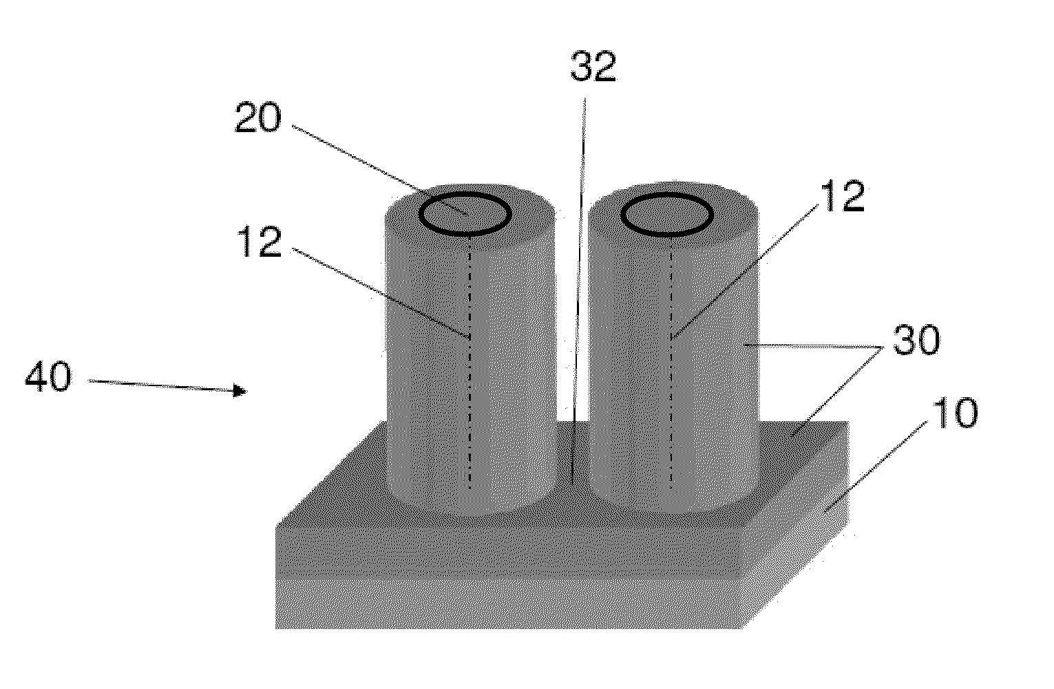
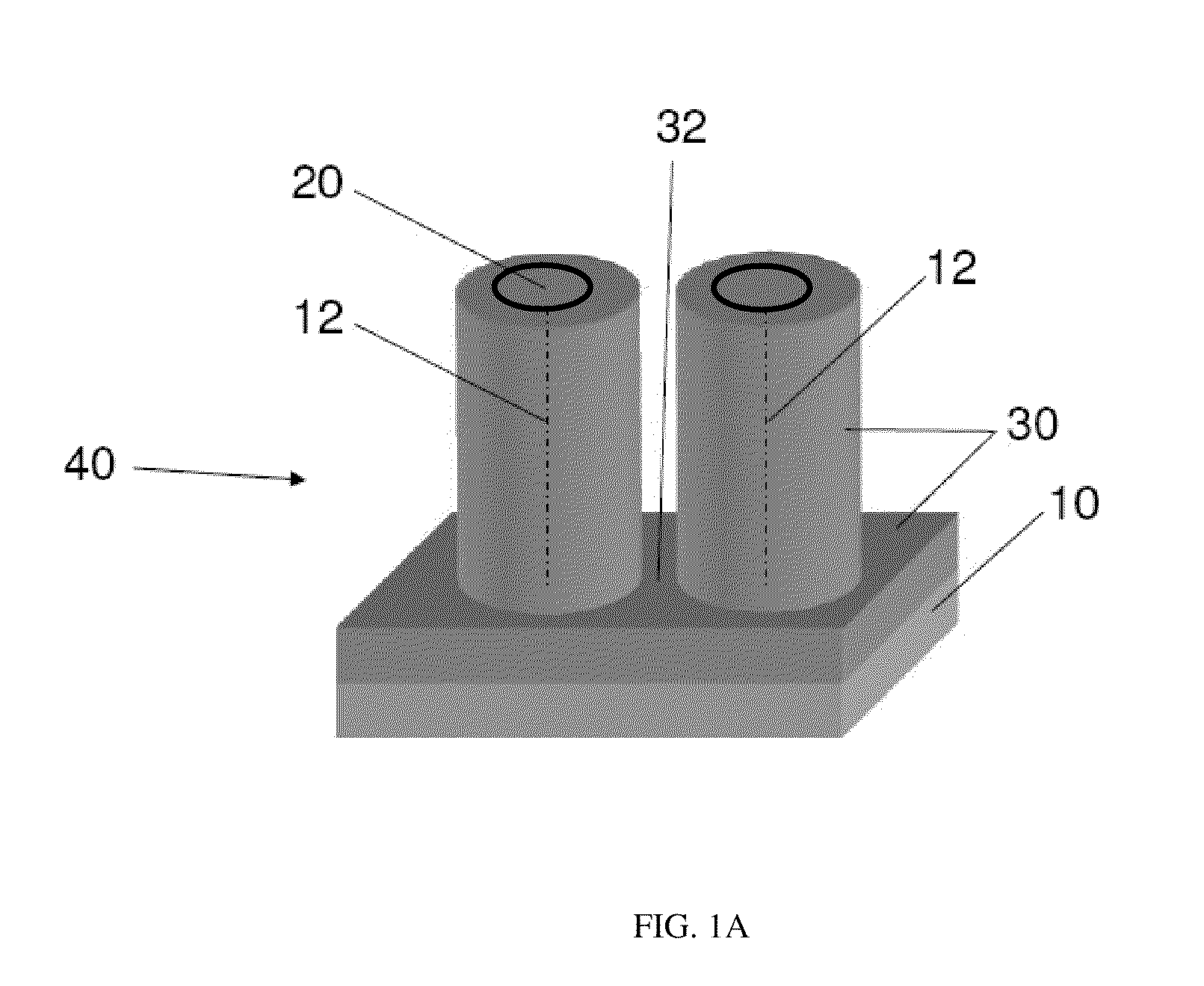
[0112]This example demonstrates the fabrication of a two-phase composite of CNTs and conducting polymers. The fabrication process is shown schematically in FIG. 19, wherein (1) carbon nanotubes are grown on a silicon substrate, (2) a conformal polymer coating is formed on the carbon nanotubes and silicon substrate, (3) the coated carbon nanotubes are removed from the substrate, and (3) characterization using SEM, TEM, FTIR, and other methods, is performed.
[0113]Multi-walled carbon nanotubes (MWNTs) were grown by thermal chemical vapor deposition (CVD) method on silicon wafers using a thin catalyst layer of Fe / Al2O3 (1 / 10 nm) deposited by electron beam evaporation. CNT growth was performed in a quartz tube furnace (22 mm ID) at atmospheric pressure. Ethylene was employed as the source of carbon for obtaining the CNTs. The typical growth temperature was 750° C., and the growth rate was 2 microns / second. Typically, CNT forests were grown on 1 cm2 silicon wafers, which resulted in well ...
example 2
[0120]This example demonstrates the fabrication of three-phase composites.
[0121]Following the deposition of PEDOT on the CNT arrays, the two-phase composites were lowered into a pool of epoxy and cured to obtain three-phase composites (comprising CNTS, PEDOT, and epoxy). CNT forests were biaxially compressed and then coated with PEDOT. The PEDOT coated forests were then lowered into a pool of uncured epoxy. An aero grade epoxy, RTM 6 (epoxy has a viscosity of 33 cP at 90° C.), was employed for this purpose. The epoxy infused into the CNT arrays through capillary driven wetting. Following the infusion of the epoxy, the entire composites were cured at 200° C. in air. As-obtained CNT arrays are referred to as 1% volume fraction, the densified CNT arrays are referred to as 5%, 8%, and 20% volume fraction. The intertube distance between conformally coated nanostructures corresponding to the volume fractions is presented in FIG. 13. As used in this Example, the “intertube distance” refers...
example 3
[0123]This example demonstrates the electrical characterization of PEDOT coated CNT three-phase composites using two-point probe electrical measurements.
[0124]In order to understand the electrical behavior of the composites, the change in the resistance of the composites with temperature was studied. The resistance measurements were performed using two-point probe measurements without the use of any additional metal contact pads. The obtained resistances were then converted into conductivity. FIG. 11 shows schematic representations of (a) a two-phase composite and (b) a three-phase composite, with the radial direction indicated by arrows. FIG. 14 shows schematic representations of (a) a two-phase composite and (b) a three-phase composite, with the axial direction indicated by arrows.
[0125]For a semi-infinite sample, the resistivity (ρ) can be obtained from the resistance (R) using the relationship ρ=RA / L. Here, L is the distance between the probes and A is the cross-sectional area. ...
PUM
| Property | Measurement | Unit |
|---|---|---|
| Length | aaaaa | aaaaa |
| Fraction | aaaaa | aaaaa |
| Fraction | aaaaa | aaaaa |
Abstract
Description
Claims
Application Information