Valve timing control apparatus

Active Publication Date: 2010-10-14
DENSO CORP
View PDF9 Cites 7 Cited by
  • Summary
  • Abstract
  • Description
  • Claims
  • Application Information

AI Technical Summary

Benefits of technology

[0023]According to a still further feature of the invention, the signal member and the spring accommodating portion may be integrally formed with each other. As a result, a number of parts and components can be reduced.
[0024]According to a still further feature of the invention, the signal member may be separately formed from the spring accommodating portion. As a result, it becomes easier to manufacture respective member and portion.
[0025]According to a still further feature of t

Problems solved by technology

It may be, therefore, difficult to exactly detect the rotational angle of

Method used


Image

  • Valve timing control apparatus
  • Valve timing control apparatus
  • Valve timing control apparatus

Examples


first embodiment

[0042]A valve timing control apparatus of the first embodiment of the present invention will be explained with reference to FIGS. 1 to 5. The valve timing control apparatus 1 according to the first embodiment is a valve timing control apparatus for an exhaust valve of an internal combustion engine for a vehicle.

[0043]As shown in FIG. 5, the valve timing control apparatus 1 is provided in a power transmitting system for transmitting a driving power of a crank shaft (a driving shaft) to an exhaust valve 97.

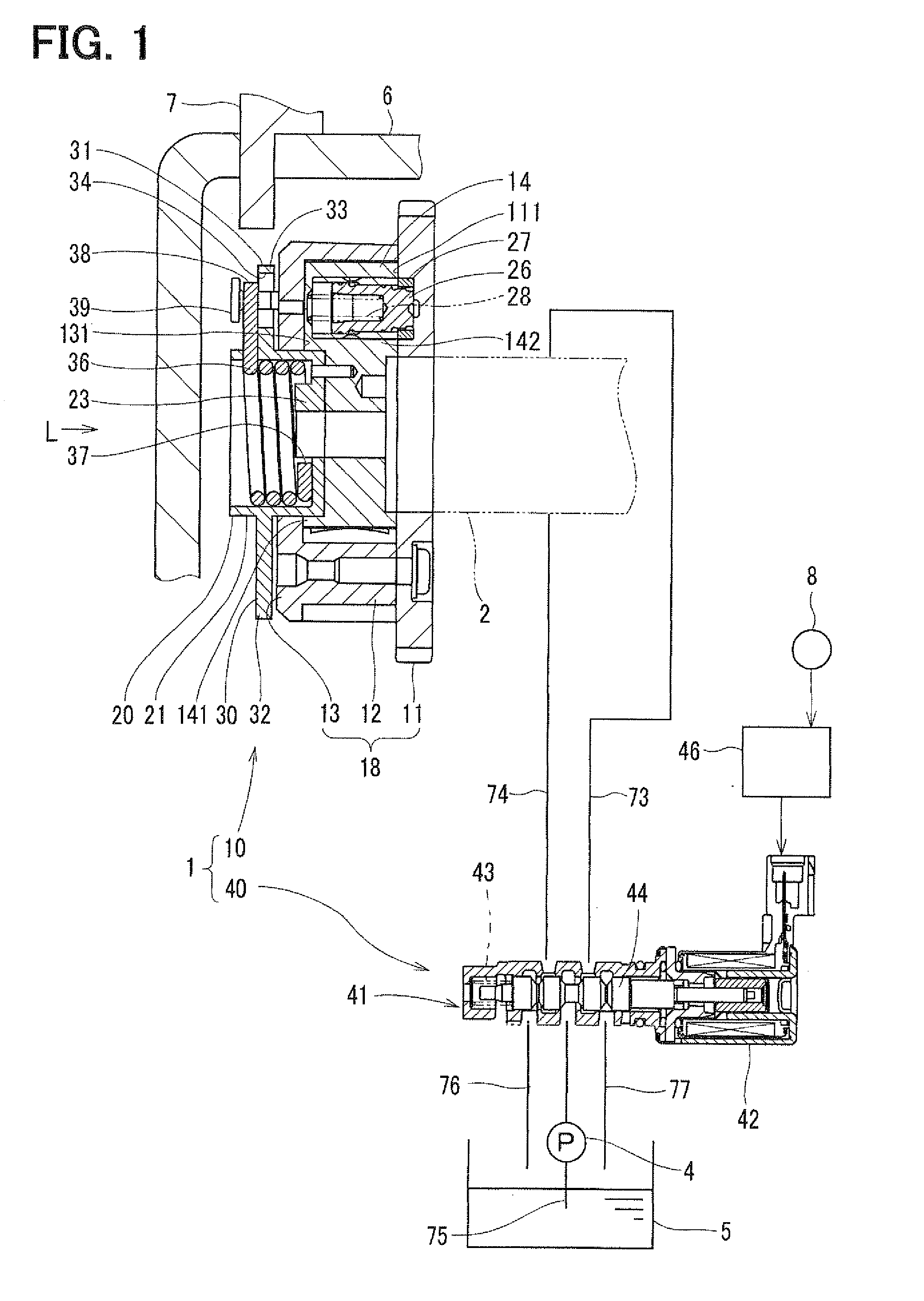
[0044]As shown in FIG. 1, the valve timing control apparatus 1 is composed of a valve timing adjusting device 10 having a cam shaft 2 (a driven shaft) and a fluid control device 40 for controlling supply of working fluid to the valve timing adjusting device 10.

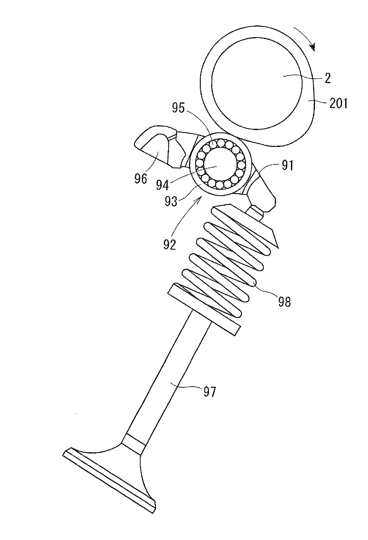
[0045]At first, the power transmitting system will be explained with reference to FIG. 5.

[0046]The power transmitting system is a roller-rocker type system, which is composed of a rocker arm 91 for transmitting the driving pow...

second embodiment

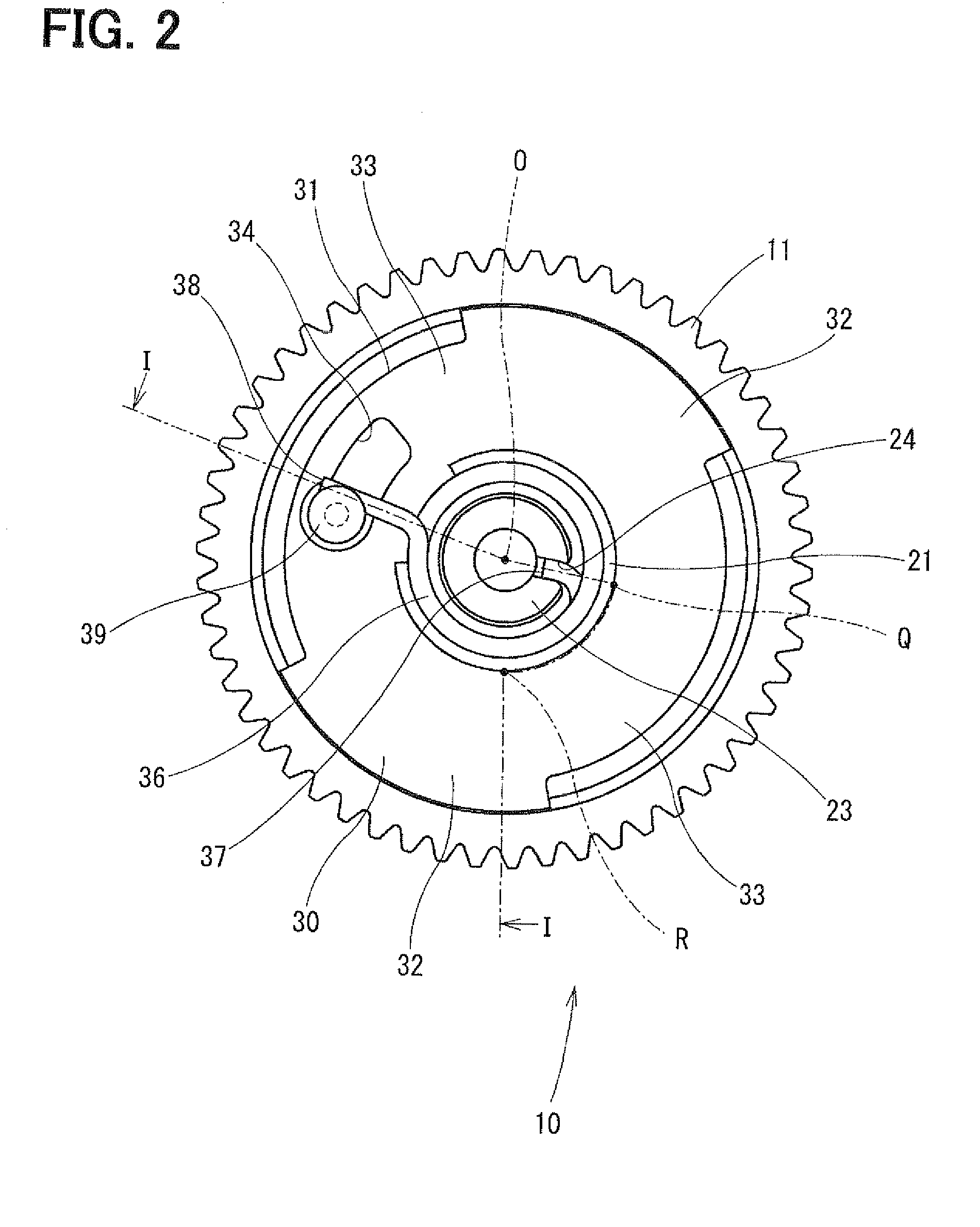
[0087]A second embodiment differs from the first embodiment in the configuration of the bush member. Different portions will be explained with reference to FIGS. 6 and 7. The same reference numerals are used in the second embodiment for such portions which are the same or similar to those of the first embodiment, and the explanation for such portions are omitted. FIG. 6 corresponds to FIG. 2 for the first embodiment, and shows the valve timing control apparatus. FIG. 7 shows a cross sectional view taken along a line VII-O-Q-R-VII in FIG. 6, wherein only the valve timing adjusting device 10 is shown.

[0088]A bush member 220, which is fixed to the boss portion 141 of the vane rotor 14, is inserted into the center through-hole formed in the front plate 13, in such a way that the bush member 220 is coaxially arranged with the front plate 13 and a relative movement between the bush member 220 and the front plate 13 is allowed. The boss portion 141 of the vane rotor 14 is fixed to the cam ...

third embodiment

[0096]A third embodiment differs from the first embodiment in the configuration of the bush member. Different portions will be explained with reference to FIGS. 8 and 9. The same reference numerals are used in the third embodiment for such portions which are the same or similar to those of the first embodiment, and the explanation for such portions are omitted. FIG. 8 corresponds to FIG. 2 for the first embodiment, and shows the valve timing control apparatus. FIG. 9 shows a cross sectional view taken along a line IX-O-Q-R-IX in FIG. 8, wherein only the valve timing adjusting device 10 is shown.

[0097]A bush member 320, which is fixed to the boss portion 141 of the vane rotor 14, is inserted into the center through-hole formed in the front plate 13, in such a way that the bush member 320 is coaxially arranged with the front plate 13 and a relative movement between the bush member 320 and the front plate 13 is allowed. The boss portion 141 of the vane rotor 14 is fixed to the cam shaf...


PUM


Abstract

An assist spring is fixed at its one end to a vane rotor and at its other end to a spring hook provided at an outside of a housing 18. A signal plate is fixed to the vane rotor on a side of the spring hook. A cam angle sensor is provided at an outer peripheral side of the signal plate for detecting a rotational angle of the signal plate. The assist spring and the spring hook are arranged in an area, which is inside of an outer periphery of the signal plate in a radial direction, so that the cam angle sensor may not misidentify the assist spring and the spring hook and thereby exactly detects the rotational angle of the signal plate.

Description

CROSS REFERENCE TO RELATED APPLICATION[0001]This application is based on Japanese Patent Application No. 2009-095030 filed on Apr. 9, 2009, the disclosure of which is incorporated herein by reference.FIELD OF THE INVENTION[0002]The present invention relates to a valve timing control apparatus for an internal combustion engine for controlling valve timing of valve opening and / or valve closing of an intake valve and / or an exhaust valve.BACKGROUND OF THE INVENTION[0003]A valve timing control apparatus is known in the art for controlling a valve opening and / or closing timing of an intake valve and / or an exhaust valve of an engine. The valve timing control apparatus has advancing oil chambers and retarding oil chambers between a vane rotor and a housing, wherein the vane rotor is movable relative to the housing. Fluid pressure of working fluid, which is supplied into the respect advancing and retarding oil chambers, is controlled so as to control a rotational phase between the vane rotor...

Claims


Application Information

Patent Timeline
IPC IPC(8): F01L1/344
CPCF01L1/022F01L1/185F01L1/3442F01L2001/34426F01L2820/041F01L2001/34469F01L2001/34483F01L2105/00F01L2001/3443F01L2305/00
Inventor TADA, KENJIUSHIDA, MASAYASU
Owner DENSO CORP
Why Eureka
Try Eureka