Method for the Collective Fabrication of Carbon Nanofibers on the Surface of Micropatterns Constructed on the Surface of a Substrate and Structure Comprising Nanofibers on the Surface of Micropatterns

a carbon nanofiber and micropattern technology, applied in the field of collective fabrication of carbon nanofibers on the surface of micropatterns, can solve the problems of inability to control the length of nanotubes, the orientation and mechanical strength of nanotubes, and the inability to etch

Active Publication Date: 2010-10-14
COMMISSARIAT A LENERGIE ATOMIQUE ET AUX ENERGIES ALTERNATIVES
View PDF7 Cites 34 Cited by
  • Summary
  • Abstract
  • Description
  • Claims
  • Application Information

AI Technical Summary

Benefits of technology

[0043]Typically, the thickness of the catalyst layer is less than roughly a few tens of nanometers, thus making the dewetting operation possible, or about fifty nanometers.

Problems solved by technology

With this method, however, a problem remains in relation to controlling the length of the nanotube, its orientation and its mechanical strength.
It is also known in the U.S. Pat. No. 7,032,437 B2 to carry out ion beam machining of the flat, leading to a non-collective growth method.The catalyst is etched, but the etching may pose a problem due to deactivation of the catalytic activity.Angle control is not possible: this is because the “oblique” deposition of the catalyst does not control the wedge shape (triangle, tip) of the catalyst.
), reorganization of the catalyst does not allow this shape to be preserved.
This method makes it possible to produce conical objects with a diameter of more than 100 nm, which leads to an imposed shape not allowing the field lines to be concentrated strongly, cylindrical shapes being more conducive to fulfilling this function.

Method used


Image

  • Method for the Collective Fabrication of Carbon Nanofibers on the Surface of Micropatterns Constructed on the Surface of a Substrate and Structure Comprising Nanofibers on the Surface of Micropatterns
  • Method for the Collective Fabrication of Carbon Nanofibers on the Surface of Micropatterns Constructed on the Surface of a Substrate and Structure Comprising Nanofibers on the Surface of Micropatterns
  • Method for the Collective Fabrication of Carbon Nanofibers on the Surface of Micropatterns Constructed on the Surface of a Substrate and Structure Comprising Nanofibers on the Surface of Micropatterns

Examples


Embodiment Construction

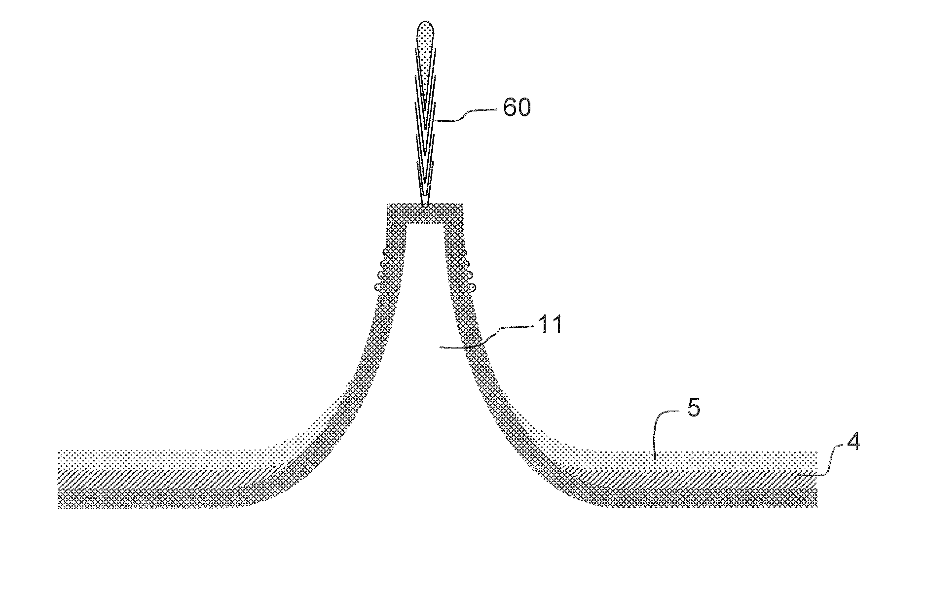
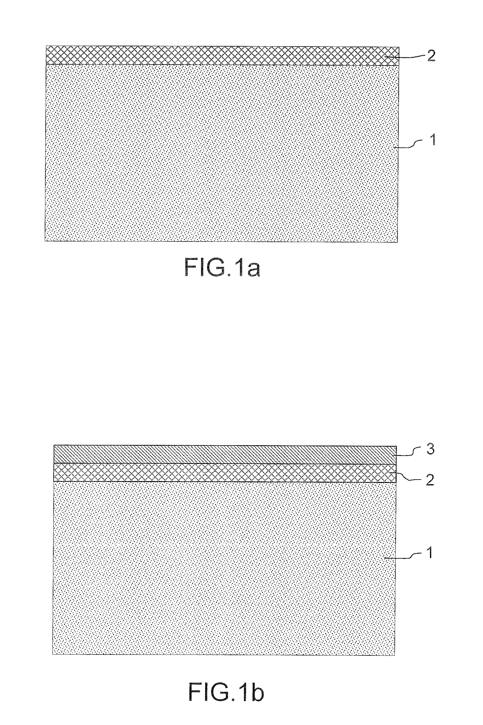
[0056]We will now describe in more detail below the various steps of the nanofiber growth method according to the invention, which is illustrated by FIGS. 1a to 1h and relates to the production of a nanofiber but could equally well be generalized to a collective nanofiber production method:

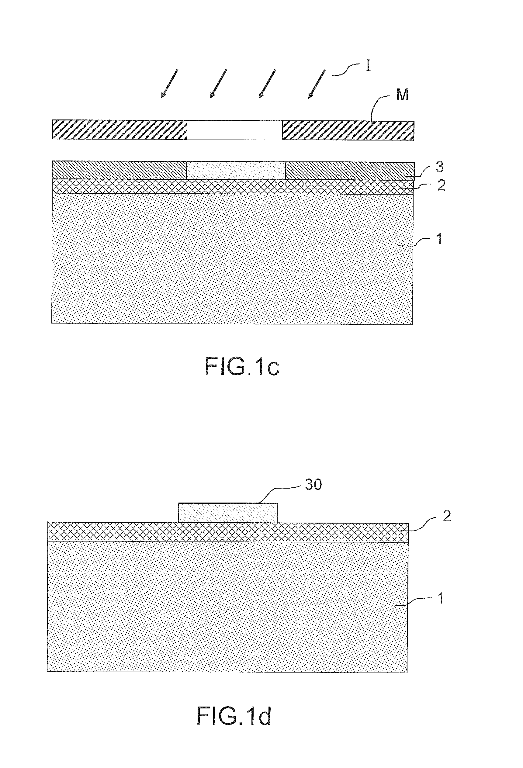
[0057]Step A: Micropattern Production:[0058]a hard mask 2 of the silicon dioxide type SiO2 and / or of the nitride type SixNy, which has a behavior in terms of etching different from that of the substrate, is deposited on a substrate 1 which may be of the Si type. FIG. 1a illustrates the stack consisting of the substrate 1 covered with the etching mask 2;[0059]a photoresistive layer 3 of the resin type is subsequently deposited, as illustrated in FIG. 1b; [0060]an exposure operation schematized by the reference I, as represented in FIG. 1c, is carried out through a photographic mask M. The purpose of the exposure is to render said photoresistive layer insoluble;[0061]the rest of the photoresistive l...


PUM

PropertyMeasurementUnit
thicknessaaaaaaaaaa
lengthaaaaaaaaaa
lengthaaaaaaaaaa

Abstract

The invention relates to a nanofiber fabrication method comprising nanofiber growth from a catalyst zone, furthermore comprising the following steps:
    • producing at least one micropattern (11) on the surface of a substrate (1);
    • producing a catalyst zone (50) on the surface of said micropattern;
    • nanofiber growth from the catalyst zone,
characterized in that the micropattern (11) comprises a base, at least partially convergent side walls and an upper face, said base being covered with a so-called “poison” layer (4) where no nanofiber growth catalysis effect can take place,
  • the so-called “poison” layer not being present on said upper face;
  • the base being covered with a catalyst layer (5) on the surface of the so-called “poison” layer;
  • the thickness of the “poison” layer and the thickness of the catalyst layer being such that the nanofibers cannot grow either on the side walls or on the base of the micropatterns constructed beforehand.
  • Description

    PRIORITY CLAIM[0001]This application claims priority to PCT Patent Application Number PCT / EP2008 / 067145, entitled Method for the Collective Fabrication of Carbon Nanofibers on the Sueface of Micropatterns Constructed on the Sueface of a Substrate and Structure Comprising Nanofibers on the Surface of Micropatterns, filed on Dec. 9, 2008.[0002]The field of the invention is that of nanofibers, and in particular carbon and silicon nanofibers, and it relates more precisely to an original collective integration method for these nanofibers.[0003]The invention aims in particular to add one or more nanofibers (carbon or silicon) to the end of a tip for near-field microscopes (SPM, Scanning Probe Microscope) by controlling:[0004]the localization of the growth by localizing the catalyst on the end of micropatterns,[0005]the rigidity of the nanofiber so that it can be used in atomic force microscopy, that is to say it does not become deformed during the measurement,[0006]the dimensions and the ...

    Claims


    Application Information

    Patent Timeline
    Patent Type & Authority Applications(United States)
    IPC IPC(8): C23F1/00B05D5/00G01Q70/12
    CPCB82Y15/00B82Y30/00G01Q70/12D01F9/127B82Y35/00
    Inventor GORINTIN, LOUISDIJON, JEANLE POCHE, HELENEMARIOLLE, DENIS
    Owner COMMISSARIAT A LENERGIE ATOMIQUE ET AUX ENERGIES ALTERNATIVES
    Why Eureka
    Try Eureka