Magnetic Tunnel Junction (MTJ) and Methods, and Magnetic Random Access Memory (MRAM) Employing Same

Active Publication Date: 2010-10-14
QUALCOMM INC
View PDF10 Cites 35 Cited by
  • Summary
  • Abstract
  • Description
  • Claims
  • Application Information

AI Technical Summary

Benefits of technology

[0010]Embodiments disclosed in the detailed description include a magnetic tunnel junction (MTJ) and methods of forming same. An MTJ may be employed in a magnetic random access memory (MRAM) bitcell to provide magnetic storage of data. The MRAM bitcell is comprised of a MTJ and an access transistor. The MTJ is comprised of an MTJ layer structure providing tunnel barrier between a first electrode and a second electrode. A free layer is disposed between the first electrode and the tunnel barrier. A reference or pinned layer is disposed between the first electrode and the tunnel barrier. Providing this MRAM bitcell structure couples the drain of the access transistor with the free layer of the MTJ. As a result, more write current can be supplied or provided by the MRAM bitcell write circuitry to switch the MTJ from a parallel (P) to an anti-parallel (AP) state. This is opposed to conventional MTJ designs that dispose the free layer above the pinned layer with the drain of the access transistor coupled to the pinned layer, where the MRAM bitcell can supply less write current to switch the MTJ from a P to AP state. By disposing the pinned layer in the MTJ such that the drain of the access transistor is coupled to the free layer as provided herein, the inherent write current characteristics of the MTJ are aligned to the write supply current capability of the MTJ when employed in an MRAM bitcell. More write current will be required to switch the MTJ from a P to AP state than from an AP to P state in both cases. As a result, more current, may be supplied to switch the MTJ from a P to AP state in the MRAM bitcell over conventional MTJ designs employed in an MRAM bitcell.
[0011]Even when disp

Problems solved by technology

If the magnetization of the pinned layer is lost, the MTJ cannot be used to retain or store information.
Thus, the AFM layer may not grow as well and may not strongly pin the edges of the pinned layer.
If a pinned layer were not provided having a pinned layer surface area g

Method used


Image

  • Magnetic Tunnel Junction (MTJ) and Methods, and Magnetic Random Access Memory (MRAM) Employing Same
  • Magnetic Tunnel Junction (MTJ) and Methods, and Magnetic Random Access Memory (MRAM) Employing Same
  • Magnetic Tunnel Junction (MTJ) and Methods, and Magnetic Random Access Memory (MRAM) Employing Same

Examples


Embodiment Construction

[0023]With reference now to the drawing figures, several exemplary embodiments of the present disclosure are described. The word “exemplary” is used herein to mean “serving as an example, instance, or illustration.” Any embodiment described herein as “exemplary” is not necessarily to be construed as preferred or advantageous over other embodiments.

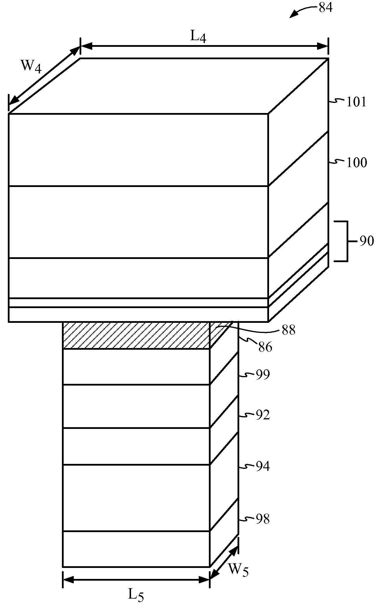
[0024]Embodiments disclosed in the detailed description include a magnetic tunnel junction (MTJ) and methods of forming same. An MTJ may be employed in a magnetic random access memory (MRAM) bitcell to provide magnetic storage of data. The MRAM bitcell is comprised of an MTJ and an access transistor. The MTJ is comprised of a MTJ layer structure providing tunnel barrier between a first electrode and a second electrode. A free layer is disposed between the second electrode and the tunnel barrier. A reference or pinned layer is disposed between the first electrode and the tunnel barrier. Providing this MRAM bitcell structure couples the drai...


PUM


Abstract

Magnetic tunnel junctions (MTJs) and methods of forming same are disclosed. A pinned layer is disposed in the MTJ such that a free layer of the MTJ can couple to a drain of an access transistor when provided in a magnetic random access memory (MRAM) bitcell. This structure alters the write current flow direction to align the write current characteristics of the MTJ with write current supply capability of an MRAM bitcell employing the MTJ. As a result, more write current can be provided to switch the MTJ from a parallel (P) to anti-parallel (AP) state. An anti-ferromagnetic material (AFM) layer is provided on the pinned layer to fix pinned layer magnetization. To provide enough area for depositing the AFM layer to secure pinned layer magnetization, a pinned layer having a pinned layer surface area greater than a free layer surface area of the free layer is provided.

Description

BACKGROUND[0001]I. Field of the Disclosure[0002]The technology of the present application relates generally to magnetic tunnel junctions (MTJ), related methods, and use of a MTJ in magnetic random access memory (MRAM).[0003]II. Background[0004]Magnetic random access memory (MRAM) is non-volatile memory in which data is stored by programming a magnetic tunnel junction (MTJ). MRAM is advantageous, because a MTJ can be used to store information even when power is turned off. Data is stored in the MTJ as a small magnetic element rather than an electric charge or current. An exemplary MTJ 10 is illustrated in FIG. 1. Data is stored in the MTJ 10 according to the magnetic orientation between two layers: a free layer 12 disposed above a fixed or pinned layer 14. The free and pinned layers 12, 14 are formed from a ferromagnetic material. The MTJ 10 is configured in a conventional “bottom-spin valve” configuration wherein the pinned layer 14 is disposed below the free layer 12. The free and ...

Claims


Application Information

Patent Timeline
IPC IPC(8): H01L29/82H01L21/00
CPCH01L27/228H01L43/08H01F10/3254H01L43/12H01F10/3272H01L43/02G11C11/16H10B61/22H10N50/80H10N50/10H10N50/01G11C11/1659G11C11/161
Inventor ZHU, XIAOCHUNNOWAK, MATTHEWLI, XIAKANG, SEUNG H.
Owner QUALCOMM INC
Why Eureka
Try Eureka