Antenna system for mobile vehicles

a technology for mobile vehicles and antenna systems, applied in the field of satellite tracking antenna systems, can solve the problems of increasing the size of the motor, increasing and increasing the weight and moment of inertia of the rotation part, so as to reduce the power consumption of the antenna system and the weight of the motor itself, the effect of reducing the capacity of the azimuth tracking motor

Inactive Publication Date: 2010-10-14
ELECTRONICS & TELECOMM RES INST
View PDF13 Cites 6 Cited by
  • Summary
  • Abstract
  • Description
  • Claims
  • Application Information

AI Technical Summary

Benefits of technology

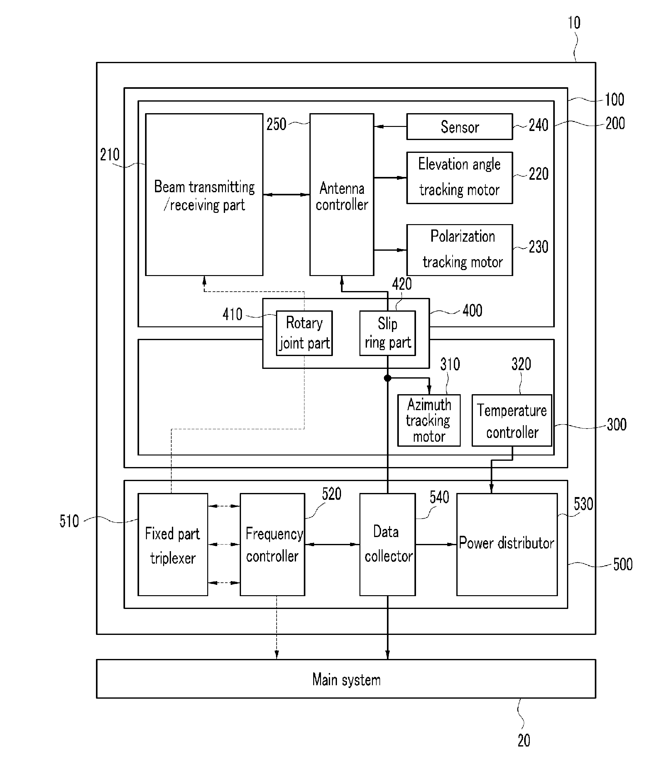
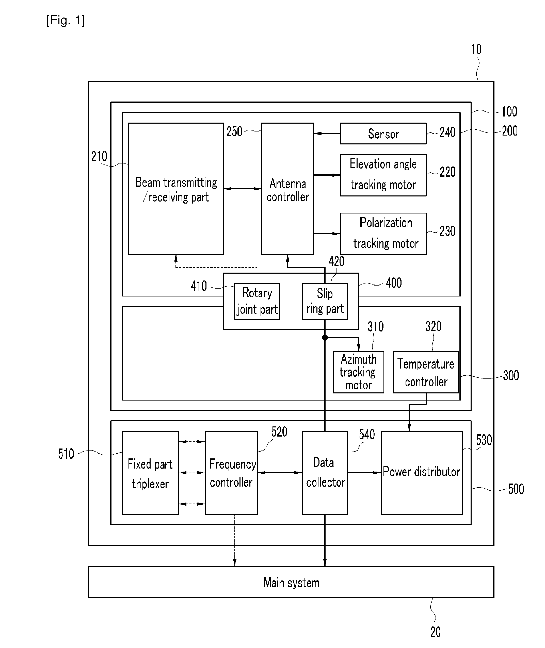
[0009]According to the present invention, modules are partially placed in the external fixed unit so that the rotation unit can be reduced in size and volume and capacity of an azimuth tracking motor that is used for controlling an azimuth of the rotation unit can be reduced, thereby reducing power consumption of the antenna system and weight of the motor itself.
[0010]In addition, the rotation unit of the antenna system is reduced in weight and volume so that it can be operated more promptly, thereby improving satellite tracking performance, and internal heat generation of the radome is significantly reduced by placing the frequency converter and the power distributor that generate a large amount of heat outside the radome, thereby reducing power consumed for controlling internal temperature of the radome.
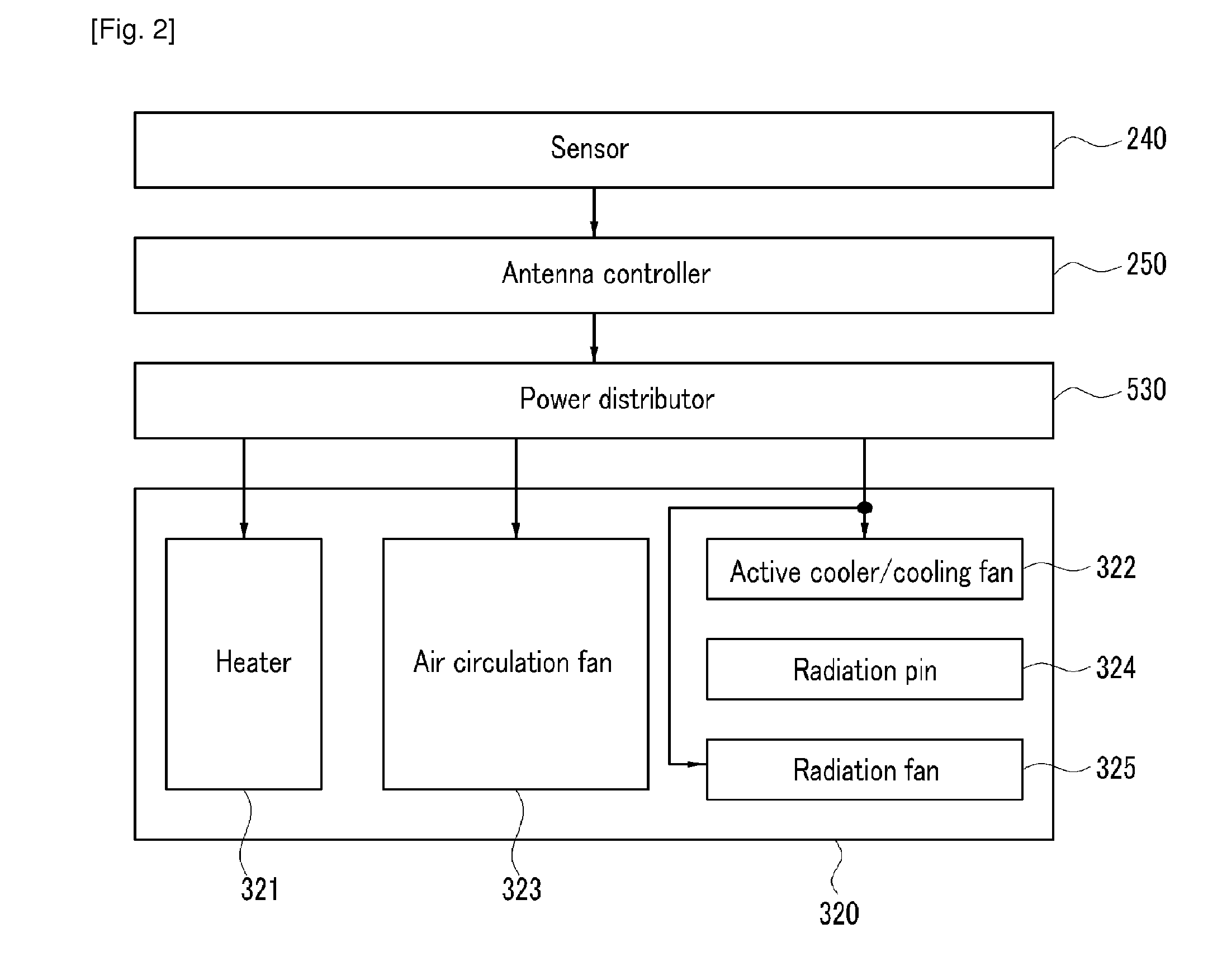
[0011]In addition, a temperature controller placed inside the radome can maintain the internal temperature of the radome within a predetermined range, thereby increasing life spans of modules and elements of the radome and preventing underperformance.

Problems solved by technology

Consequently, the weight and moment of inertia of the rotation part increase and the size of a motor is increased for high speed tracking of the satellite, and accordingly, the antenna system consumes more power.
Therefore, when outdoor temperature is high, heat generated from internal parts of the radome cannot be transmitted to the outside quickly enough so the internal temperature of the radome becomes higher than the outdoor temperature, thereby causing damage to the performance and life span of the antenna.
When the outdoor temperature is low, in spite of disconnection between the inside of the radome and the outside of the radome, heat generated by internal modules may not be enough to raise internal temperature to the operating range if the vehicle moves so fast that the boundary layer of the air on the outer surface of the radome gets very thin.

Method used


Image

  • Antenna system for mobile vehicles
  • Antenna system for mobile vehicles
  • Antenna system for mobile vehicles

Examples


Embodiment Construction

[0014]In the following detailed description, only certain exemplary embodiments of the present invention have been shown and described, simply by way of illustration. As those skilled in the art would realize, the described embodiments may be modified in various different ways, all without departing from the spirit or scope of the present invention. Accordingly, the drawings and description are to be regarded as illustrative in nature and not restrictive. Like reference numerals designate like elements throughout the specification.

[0015]Throughout this specification and the claims which follow, unless explicitly described to the contrary, the word “comprising” and variations such as “comprises” will be understood to imply the inclusion of stated elements but not the exclusion of any other elements. Also, the terms of a unit, a device, and a module in the present specification represent a unit for processing a predetermined function or operation, which can be realized by hardware, so...


PUM


Abstract

The present invention relates to an antenna system mounted on a mobile vehicle. In the present invention, a power distributor and a part of a high-frequency module that includes a frequency converter are placed in an external fixed unit that is placed outside a radome. In addition, an active cooler / cooling fin, a heater, and an air circulation fan are placed at an internal bottom plane of the antenna system, and a cooling fin and cooling fan are placed at an external bottom plane of the antenna system.

Description

TECHNICAL FIELD[0001]The present invention relates to an antenna system. Particularly, it relates to a satellite tracking antenna system mounted on a mobile vehicle.[0002]The present invention was supported by the IT R&D program of MIC / IITA [2006-S-020-02, Development of Satellite and Terrestrial Convergence Technology for Internet Service on High-speed Mobile Vehicles].BACKGROUND ART[0003]In general, a satellite tracking antenna mounted on a mobile vehicle includes a rotation part for tracking a satellite and a fixed part to be mounted on a mobile vehicle. Most of constituent elements of the antenna system are placed in the rotation part, excluding a triplexer that is placed in the fixed part. Consequently, the weight and moment of inertia of the rotation part increase and the size of a motor is increased for high speed tracking of the satellite, and accordingly, the antenna system consumes more power.[0004]The satellite tracking antenna system mounted on the mobile vehicle is gene...

Claims


Application Information

Patent Timeline
Patent Type & Authority Applications(United States)
IPC IPC(8): H04B7/185H01Q3/00
CPCH01Q1/002H01Q3/08H01Q1/27H01Q1/02H01Q1/42
Inventor KWAK, CHANG SOOYOM, IN BOKLEE, HO JIN
Owner ELECTRONICS & TELECOMM RES INST
Why Eureka
Try Eureka