Apparatus for Testing Infrared Sensors

a technology for infrared sensors and apparatuses, applied in the direction of heat measurement, optical radiation measurement, instruments, etc., can solve problems such as complex mechanical manipulation

Active Publication Date: 2010-10-14
ANALOG DEVICES INC
View PDF5 Cites 16 Cited by
  • Summary
  • Abstract
  • Description
  • Claims
  • Application Information

AI Technical Summary

Benefits of technology

[0009]In embodiments of the invention, a heater element can be part of the apparatus and used for heating the heat mass to the heat mass temperature, which may be above ambient temperature. The heat mass can thus provide the infrared source with a temperature above ambient temperature, which helps ensure that the infrared sensor is sensing the radiation from the infrared source, and not background radiation. The apparatus also may include an infrared filter for filtering the test signal before it reaches the infrared sensor, which can further ensure that the infrared sensor properly senses the desired radiation source. The apparatus also may include a light pipe for filtering out reflected and refracted infrared signals, so that only parallel infrared waves from the test signal reach the infrared sensor. The apparatus also can include a temperature sensor for measuring a sensed temperature of the heat mass, and a temperature processor for receiving the sensed temperature and adjusting a temperature setting signal to the heat source until the sensed temperature equals the first temperature in a feedback loop. Accordingly, the temperature of the heat mass can be kept substantially constant, contributing to a more stable test environment.
[0018]In a related embodiment, the method also includes stimulating the infrared source with a second electrically modulated signal producing a second infrared test signal, receiving a second sensor signal from the infrared sensor of the integrated circuit in response to the second infrared test signal, and processing the second sensor signal to isolate modulated information representative of the second infrared test signal. In this way, the infrared sensor can be tested at multiple test temperatures.

Problems solved by technology

ATE does not have the capability to test infrared sensors using traditional pin tester boards and therefore, any chips that employ infrared sensors presently need to be disconnected from the ATE and attached to a separate infrared tester.
In order to test an IR sensor at two temperatures, two different blackbodies would need to be used, requiring complex mechanical manipulation.

Method used


Image

  • Apparatus for Testing Infrared Sensors
  • Apparatus for Testing Infrared Sensors
  • Apparatus for Testing Infrared Sensors

Examples


Embodiment Construction

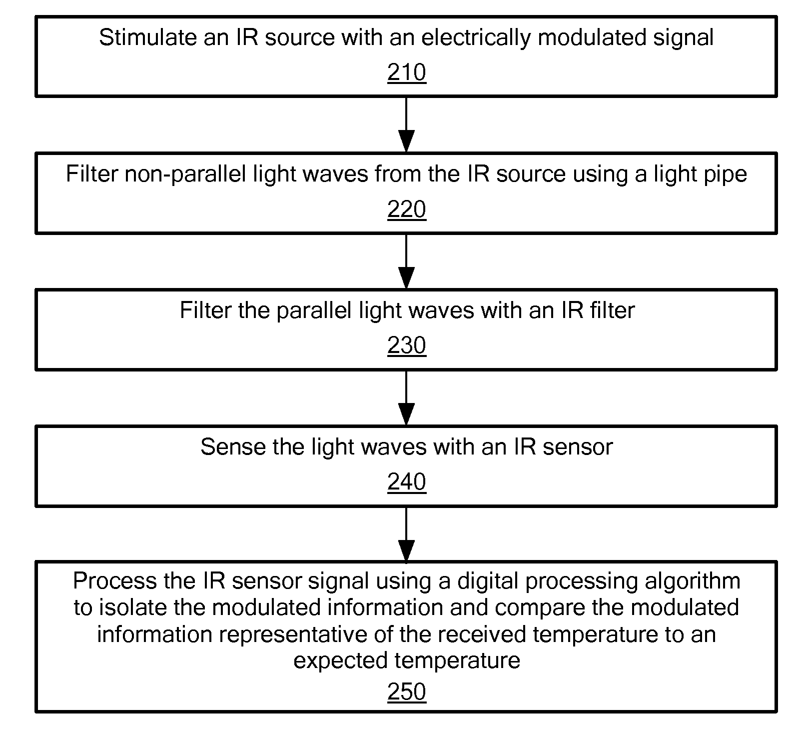
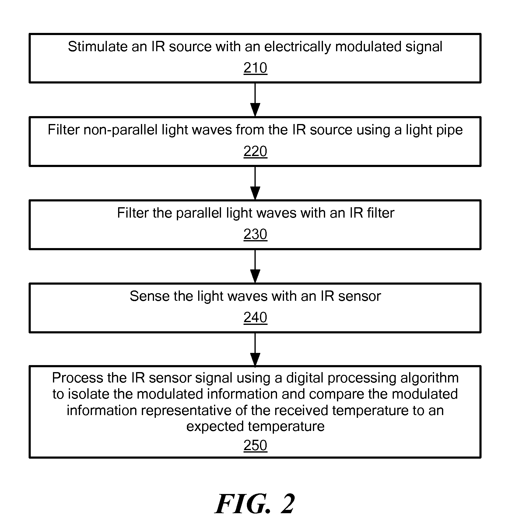
[0025]FIG. 2 shows a flow chart of the methodology employed in creating a stable production environment for testing infrared sensors. As a preparatory step, a DUT containing an infrared sensor is placed in automatic test equipment (ATE). More than one DUT may be placed into the test environment at a time and the DUTs may be tested in parallel. In such an environment, each DUT would be associated with a separate IR source. In process 210 the IR source associated with the DUT is stimulated with an IR test signal modulated at a predetermined frequency for a specific test temperature. The test temperature may be associated with the peak power of a periodic waveform, such as a sinusoid. The IR source produces an IR signal at the desired temperature. The temperature is related to the power output and can be controlled by limiting the voltage amplitude. Accordingly, in some embodiments a single IR source may be used to simulate multiple temperatures in sequence by adjusting the voltage amp...


PUM

PropertyMeasurementUnit
thermal time constantaaaaaaaaaa
temperatureaaaaaaaaaa
time constantaaaaaaaaaa

Abstract

An apparatus for use with automatic testing equipment for testing infrared sensors on integrated circuits is provided. The apparatus includes an infrared source, a heat mass, and an electronic frequency modulator. The infrared source is modulated according to a predetermined test frequency such that the infrared source emits an infrared test signal representative of a test temperature and corresponding to the temperature of the heat mass and the predetermined test frequency. A signal processor, electrically coupled to an integrated circuit having an infrared sensor, receives a sensed signal from the infrared sensor in response to the infrared test signal and uses the sensed signal according to the predetermined test frequency to determine a measured temperature.

Description

TECHNICAL FIELD[0001]The present invention relates to automatic testing equipment, and more particularly to testing of infrared sensors.BACKGROUND ART[0002]It is known in the prior art to test integrated circuits using automatic testing equipment (ATE). ATE employ channel cards that include a plurality of pin electronics to test each channel / pin of an integrated circuit, which is referred to as a device under test (DUT). Standard in most pin electronics are a comparator circuit for comparing the input from the pin under test to an expected value, a driver circuit for testing a condition on a pin, an active load for simulating a changing signal, and a precision pin measurement unit (“PPMU”) for performing accurate pin tests of AC signals. Each of the four described elements is employed with a separate circuit. Each pin tester board can test at least one pin of the DUT. In some instances, a pin tester board is configured to test only a single pin of a device under test.[0003]With the ...

Claims


Application Information

Patent Timeline
Patent Type & Authority Applications(United States)
IPC IPC(8): G01K15/00G01D18/00
CPCG01D1/00G01D15/00G01J1/08G01J5/0096G01J2005/068G01J5/08G01J5/0896G01J5/522G01J5/061G01J5/064G01J5/53
Inventor GRUBB, JOHNBLANEY, GERARDCULHANE, EAMON
Owner ANALOG DEVICES INC
Why Eureka
Try Eureka