

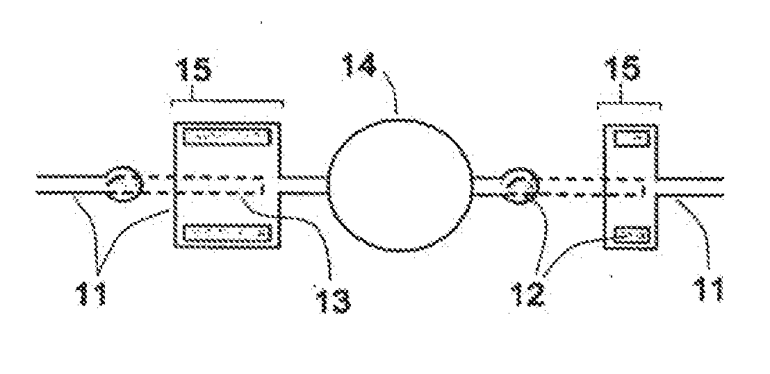
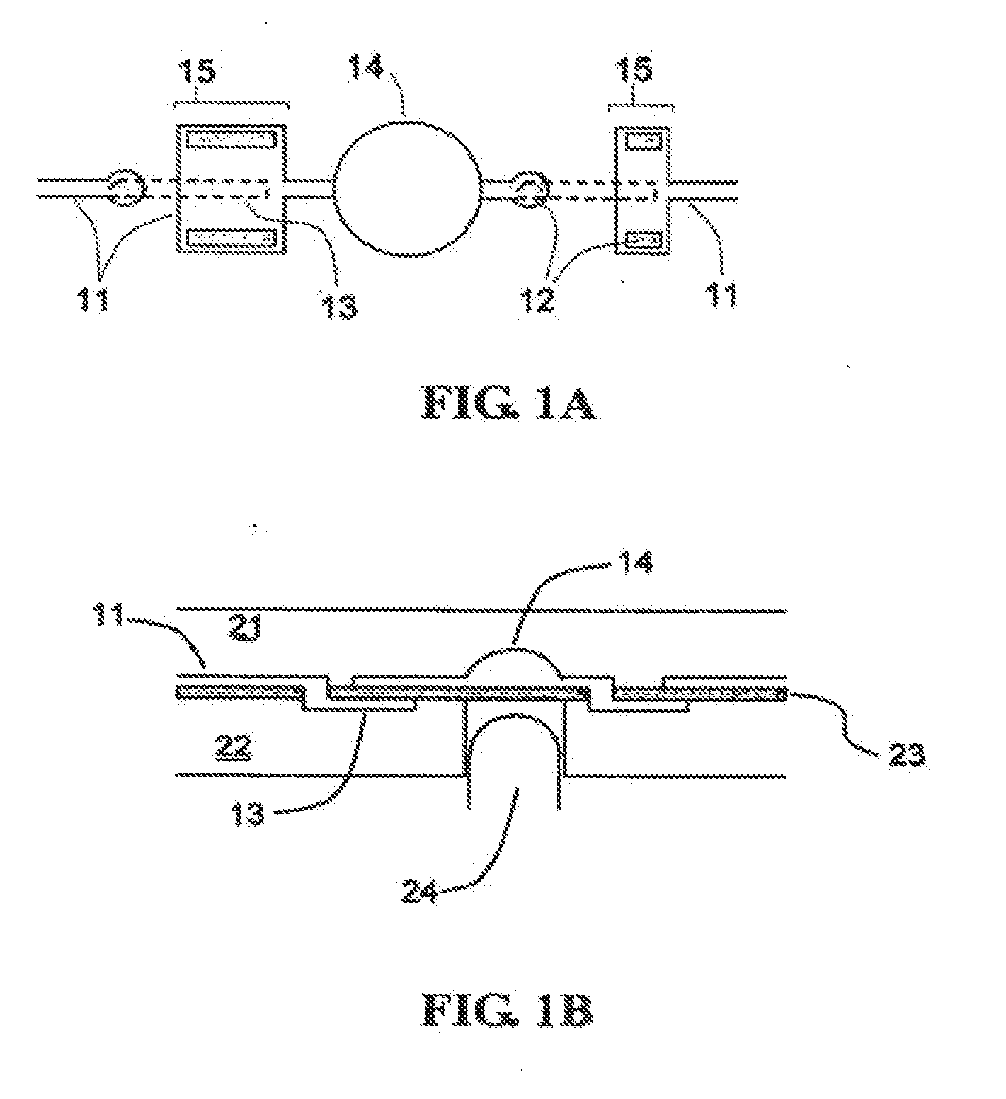
Valve Structure for Consistent Valve Operation of a Miniaturized Fluid Delivery and Analysis System
a fluid delivery and analysis system technology, applied in the direction of check valves, machines/engines, biomass after-treatment, etc., can solve the problem of inherently unidirectional pumping structures, achieve the effect of eliminating all alignment effects on the valve, improving consistency, reliability and manufacturability of biological immunoassay cartridges
- Summary
- Abstract
- Description
- Claims
- Application Information
AI Technical Summary
Benefits of technology
Problems solved by technology
Method used
Image

Examples
example 1
[0036]Immunological Assay
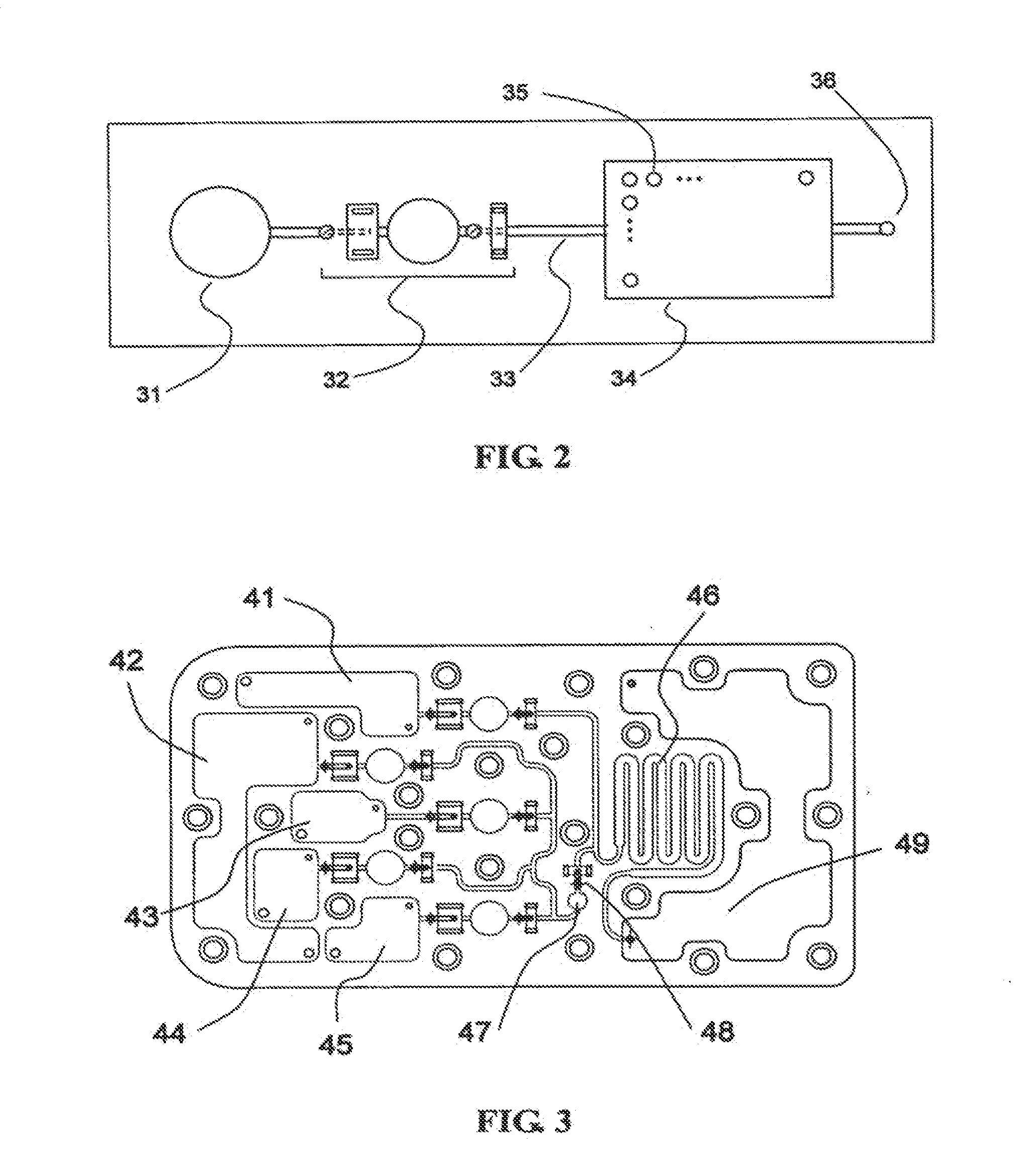
[0037]The plastic fluidic cartridge, as shown in FIG. 2, can be utilized to perform immunological assays within reaction chamber 34 by immobilizing a plurality of bio-molecules such as different antibodies 35. In one exemplary embodiment, a sample containing an unknown concentration of a plurality of antigens or antibodies is first placed within reservoir 31. The external linear actuator is then repeatedly actuated to pump the sample from reservoir 31 to reaction chamber 34. The sample is then allowed to react with the immobilized antibodies 35 for a set reaction time. At the end of the set reaction time, the sample is then excluded from reaction chamber 34 through exit port 36. A wash buffer is then placed in reservoir 31 and the external linear actuator is repeatedly actuated to pump the wash buffer through reaction chamber 34 and out the exit port 36. Such wash steps can be repeated as necessary. A solution containing a specific secondary antibody conjuga...
example 2
[0040]DNA Hybridization
[0041]The system of the present invention can also be used to perform DNA hybridization analysis. Using the plastic cartridge of FIG. 4, a plurality of DNA probes are immobilized in reaction chamber 55. A sample containing one or more populations of fluorescently tagged, amplified DNA of unknown sequence is placed in reservoir 52. A first stringency wash buffer is placed in reservoir 51. A second stringency wash buffer is placed in reservoir 53. Reaction chamber 55 is maintained at a constant temperature of 52.degree. C. The sample is transferred to circulation reservoir 56 by repeatedly actuating a linear actuator corresponding to a pump structure connected to reservoir 52. The sample is then circulated through reaction chamber 55 by repeatedly actuating a linear actuator corresponding to pump structure 57. The sample is circulated continuously for a predetermined hybridization time typically from 30 minutes to 2 hours. The sample is then excluded from the ci...
PUM
| Property | Measurement | Unit |
|---|---|---|
| Flow rate | aaaaa | aaaaa |
| Flexibility | aaaaa | aaaaa |
| Torque | aaaaa | aaaaa |
Abstract
Description
Claims
Application Information