Method and apparatus for forming containers with corrugated material

a technology of corrugated material and forming method, which is applied in the direction of paper/cardboard containers, containers, packaged goods, etc., can solve the problems of significant increase in shipping costs, inability to adapt pre-folded and pre-glued blanks to shipping in bulk, and drawbacks in the process of forming and packing rscs, etc., to achieve the effect of cheaper manufacturing and equivalent or better strength

Active Publication Date: 2010-10-21
LANGEN H J PAUL
View PDF16 Cites 31 Cited by
  • Summary
  • Abstract
  • Description
  • Claims
  • Application Information

AI Technical Summary

Benefits of technology

[0017]Accordingly, a new blank design, designated by the applicant as a dual side seam-regular slotted container blank (the “DSS-RSC” (TradeMark) blank) has been devised along with new forming processes and systems suited to forming cases from DSS-RSC blanks. The DSS-RSC blank that has been conceived can be formed into a DSS-RSC case that is functionally equivalent to an RSC case, but may be both cheaper to manufacture than an RSC, and may provide equivalent or better strength than an RSC.

Problems solved by technology

There are however significant drawbacks to the process of forming and packing the RSCs.
For example, the pre-folded and pre-glued blanks are not well adapted to shipping in bulk from the location where the knock-downs are formed to the premises where the knock-downs are erected and packed, due to their asymmetric shape—being three layers thick on the glued seam area and only two layers thick elsewhere.
These factors result in a significant increase in shipping costs compared to blanks that can be shipped in a completely flat arrangement.
Other problems associated with the formation of a RSC relate to the creation of the knock-down RSC.
The alignment and gluing that is done to form the “knock-down” is often not very accurately performed and so the RSC that is eventually formed may not be properly and accurately constructed.
This may cause problems in the erection of the case and in the loading and storage of items in the RSC.
RSC cases may be preferred because hand packing can be easily done if problems with machinery arise; (2) The machinery traditionally used to form and pack die cut cases from flat, die cut blanks has been more expensive, complex, and inflexible when compared to RSC erectors and packers.
Businesses that have invested in RSC-type machinery have not see the need to invest the time and money to move to an alternate system based on a flat die cut blank, in the absence of significant cost savings and a viable alternate system for forming and packing such a case.

Method used


Image

  • Method and apparatus for forming containers with corrugated material
  • Method and apparatus for forming containers with corrugated material
  • Method and apparatus for forming containers with corrugated material

Examples


Embodiment Construction

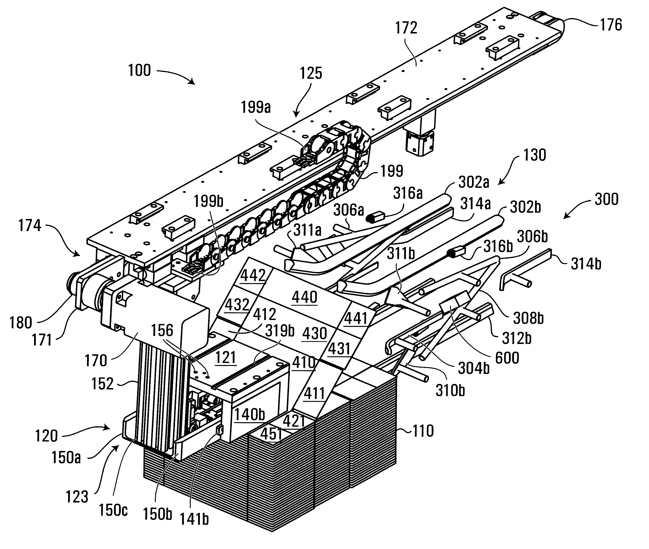
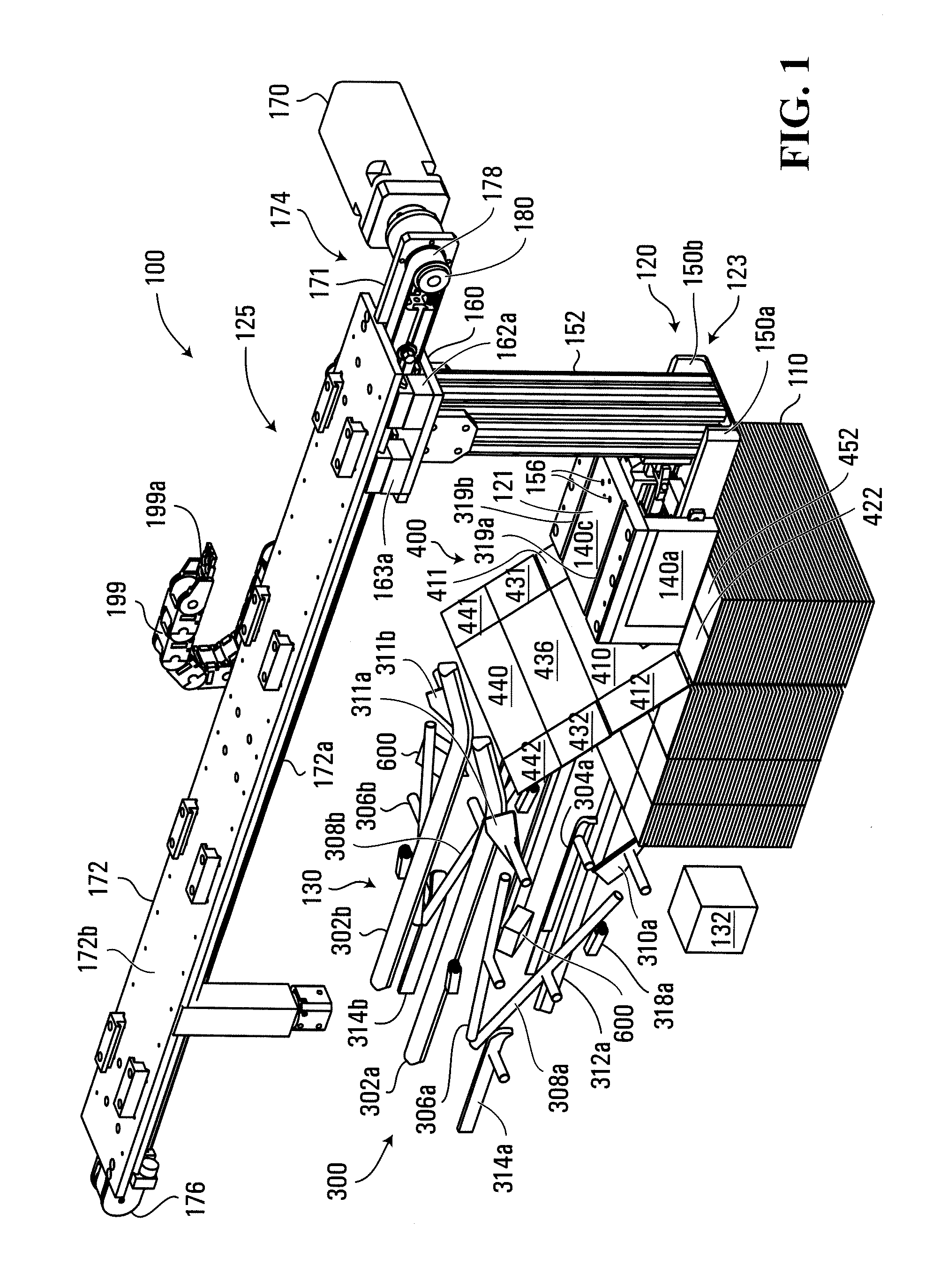
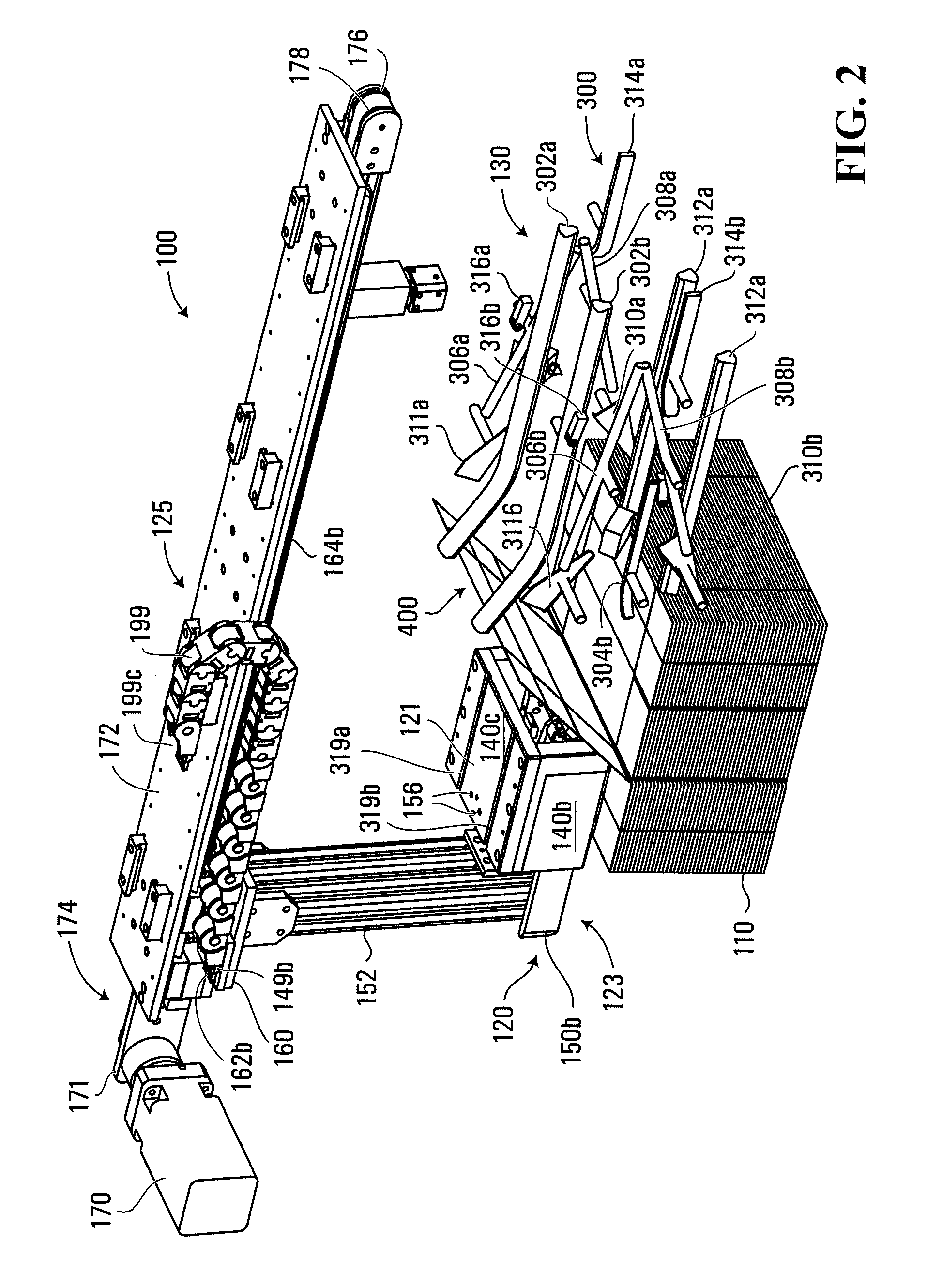
[0053]With reference initially to FIG. 28, a process for forming and packing a DSS-RSC case with items is illustrated schematically. The first step 1000 is the formation of a corrugated sheet of material (that may be formed into a roll of material) from which the DSS-RSC blank will be made. The roll or sheet of corrugated material does not have to be of the specific width or length of the desired width and length of the DSS-RSC blank such as blank 400 as illustrated in FIG. 30. The corrugated roll or sheet of fibreboard can be formed using a known type of corrugator machine such as the BHS Corrugator machine made by BHS Corrugated Maschinen- and Anlagenbau GmbH. An example of the type of corrugated sheet of material that may be produced is described in U.S. Pat. No. 150,588 the entire contents of which are hereby incorporated herein by reference. Step 1000 will typically take place in a plant location that is dedicated to manufacturing sheets / rolls of corrugated materials.

[0054]Once...


PUM

PropertyMeasurementUnit
angleaaaaaaaaaa
widthaaaaaaaaaa
lengthaaaaaaaaaa

Abstract

A case is disclosed that is made from a corrugated material and has a generally flat transversely extending base panel and first and second transversely extending, generally parallel, side wall panels upstanding from, and being oriented generally orthogonal to, the base panel. First and third end wall panels meet at a first vertically extending seam extending upwards from one end of the base panel and second and fourth end wall panels meet at a second vertically extending seam extending upwards from an opposite end of the base panel. A blank for forming such a case is also disclosed. A method comprises forming a sheet of corrugated fiberboard; operating a die cutting apparatus to form a generally flat case blank from the sheet of corrugated fiberboard at a first location; transporting the flat case blank to a second location; operating a case forming apparatus at the second location to fold the case blank to form the case; after the case has been formed by the case forming apparatus, operating a loading apparatus to load at least one item into the case; and sealing opposed top panels.

Description

RELATED APPLICATIONS[0001]This application is a continuation-in-part of international application PCT / CA2009 / 001249, filed Sep. 11, 2009, which claims the benefit of and priority from U.S. provisional patent application No. 61 / 136,542, filed on Sep. 12, 2008, the entire contents of both of which are incorporated herein by reference.FIELD OF THE INVENTION[0002]The present invention relates generally to methods and systems for forming containers made from corrugated material, including corrugated fibreboard.BACKGROUND OF THE INVENTION[0003]Containers are used to package many different kinds of items. One form of container used in the packaging industry is a case that is used for shipping items / products. In the present application, the term “case” is used to refer to such containers. Cases come in many different configurations and are made from a wide variety of materials. However, many cases are foldable and are formed from a flattened state (commonly called a case blank). Cases may b...

Claims


Application Information

Patent Timeline
Patent Type & Authority Applications(United States)
IPC IPC(8): B65B5/02B65D5/20B65B43/10B31B1/26B31B1/62B31B50/02B31B50/20B31B50/62B31B50/80
CPCB31B1/06B65D5/42B31B1/46B31B3/00B31B2201/0264B31B2201/2654B31B2201/2666B65D5/20B31B1/02B65D5/02B31F1/20B31B5/76B31B1/74B31B1/26B31B1/20B31B1/44B31B50/022B31B50/06B31B50/44B31B50/46B31B50/26B31B50/74B31B50/76B31B2100/00B31B2120/30
Inventor LANGEN, H. J. PAUL
Owner LANGEN H J PAUL
Why Eureka
Try Eureka