Apparatuses For and Methods of Forge Welding Elongated Articles with Electrodes and an Induction Coil

Inactive Publication Date: 2010-10-21
AMR ENG
View PDF7 Cites 5 Cited by
  • Summary
  • Abstract
  • Description
  • Claims
  • Application Information

AI Technical Summary

Benefits of technology

[0017]It is an object of the present invention to provide an apparatus and method for forge welding that improved temperature control of the articles

Problems solved by technology

Also the material properties may affect viscoplastic deformation and be a cause of variability, which must be detected and compensated for.
A too high temperature may cause undesirable melting or excessive grain growth while a too low temperature will unavoidably lead to insufficient reduction of surface oxides and poor bounding.
Undesirable material phase shifts and brittleness may also be the result of poor temperature control during heating and cooling.
A large input of heat during the heating stage of the process will produce a heated zone of large extent and cause slow cooling of the material after welding.
This may be a problem particularly when welding metals that must be quenched and tempered in order to establish sufficient ductility for a giv

Method used


Image

  • Apparatuses For and Methods of Forge Welding Elongated Articles with Electrodes and an Induction Coil
  • Apparatuses For and Methods of Forge Welding Elongated Articles with Electrodes and an Induction Coil
  • Apparatuses For and Methods of Forge Welding Elongated Articles with Electrodes and an Induction Coil

Examples


Embodiment Construction

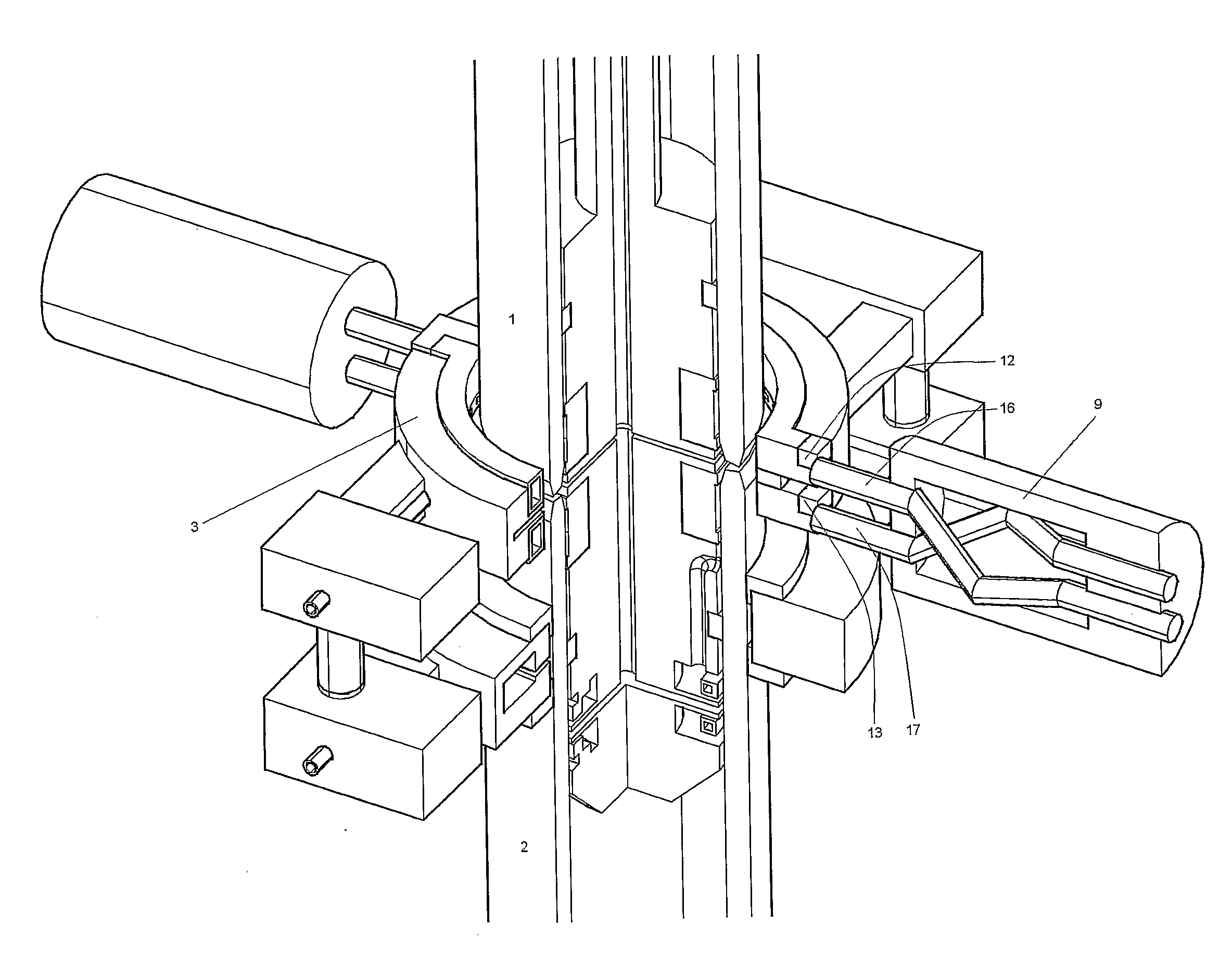
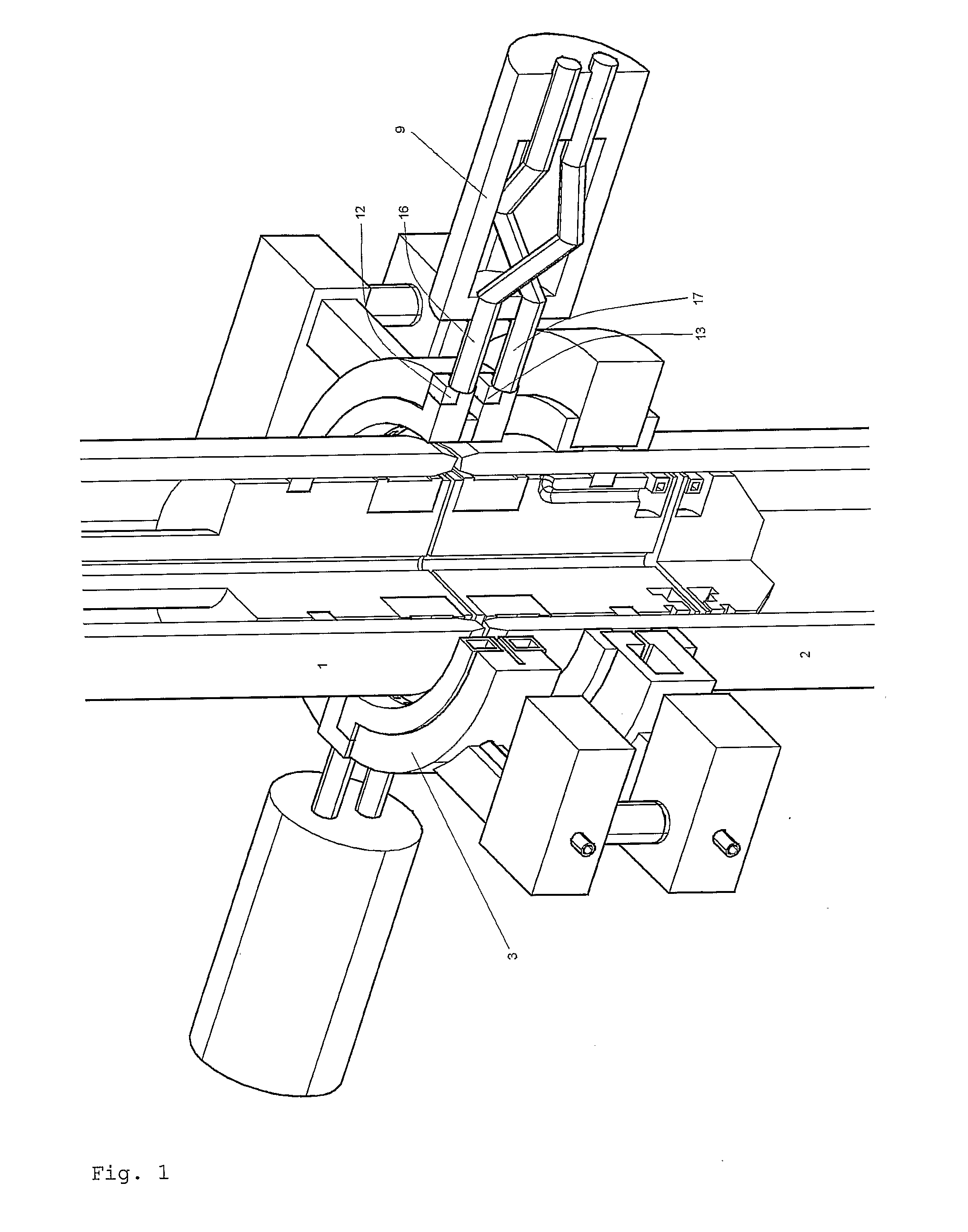
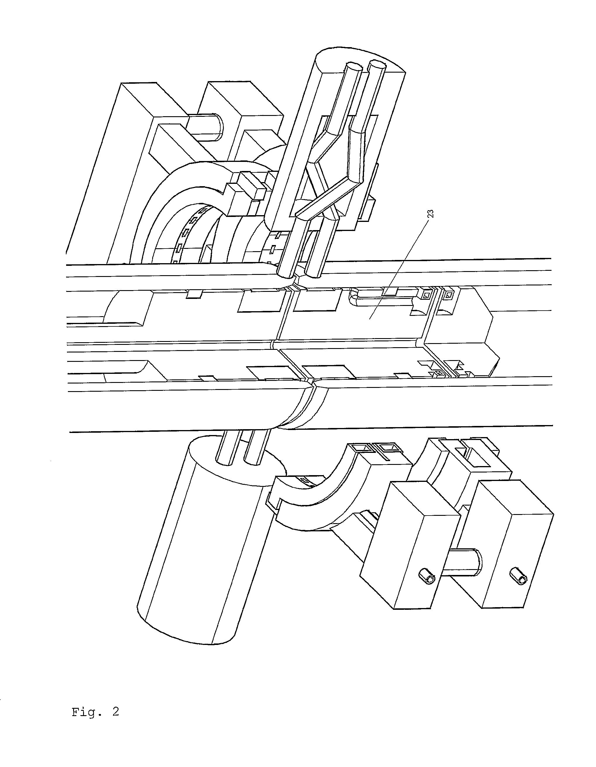
[0025]The induction heating arrangement may be realized in at least two different embodiments:[0026]1. A two-part coil that shares the transformer supplying the contact assemblies. This is illustrated in FIGS. 1-4. Here, the coil part 3a is equipped with contact pads 12, 13. During induction heating, the contact assembly 8 is pushed towards the contact pads 12, 13. The other contact assembly 9 is pushed towards corresponding contact pads on the other coil half 3b. It is a large benefit to avoid a dedicated transformer for feeding the coil, as this component is very bulky and takes up a lot of room. It is also expensive.[0027]2. A four-part coil supplied with current from the transformer(s) supplying the contact assemblies, in which coil segments are fastened to the tips of the contacts. In this case, contact gaps 14, 15 are arranged in the coil. The contact gaps are closed before current is applied. This embodiment is illustrated in FIG. 5.

[0028]FIG. 1-4 illustrates a welding sequen...


PUM

PropertyMeasurementUnit
Timeaaaaaaaaaa

Abstract

The present application relates to an apparatus for and a method of forge welding elongate articles (1, 2), such as tubes, together. In addition to electrode (12, 13) assemblies (9) for heating the article (1, 2) ends with high frequency resistive heating, the apparatus includes a coil (3) for induction heating the articles (1, 2) before or after welding, as well as means for cooling the welding seam.

Description

FIELD OF THE INVENTION[0001]The present invention relates to welding articles in general and in particular the welding of solid and hollow sections such as oil field tubes and water pipe lines.TECHNICAL BACKGROUND[0002]The present invention relates to a method for forge or enhanced diffusion welding of two or more metal parts, wherein at least one joint is established between opposed bounding surfaces on the parts to be joined. One such method denoted Shielded Active Gas Forge Welding (SAG-FW) known from, and to a large extent defined by, U.S. Pat. Nos. 4,669,650 and 4,736,084 includes the following features:[0003]1. The welding process consists of four main stages wherein the metal parts are:[0004]a. heated electromagnetically to high local temperatures,[0005]b. brought rapidly into close contact,[0006]c. forged together until a metallic bound is established, and[0007]d. cooled by convection, radiation and conduction[0008]2. The metal parts have been carefully shaped so that there ...

Claims


Application Information

Patent Timeline
IPC IPC(8): H05B6/10B23K31/02
CPCB23K11/0935B23K13/01B23K2201/06B23K20/02B23K20/14B23K20/008B23K2101/06
Inventor MOE, PER THOMASHALMRAST, BJORN
Owner AMR ENG
Why Eureka
Try Eureka