Fiber reinforced composite cores and panels

a fiber reinforced composite core and core technology, applied in the field of composite structures of sandy panels, can solve the problems of reducing the dimensions of the core components, increasing the difficulty of processes, and limited impact damage to the immediate area, so as to improve the buckling resistance of the unidirectional core, reduce the effect of impact damag

Inactive Publication Date: 2010-10-21
METYX USA INC
View PDF62 Cites 83 Cited by
  • Summary
  • Abstract
  • Description
  • Claims
  • Application Information

AI Technical Summary

Benefits of technology

[0027]An important advantage of all of the bi-directional cores described herein is that the intersecting reinforcing webs stabilize each other against buckling under load into the adjacent low density and low strength foam strip. Web buckling resistance in unidirectional cores may be improved by increasing the effective width of the web by providing a spacer strip, for example high density foam plastic, between adjacent wound foam strips. In an economical form of unidirectional core panel, roving-wound foam strips alternate with plain foam strips, thus permitting the doubling of panel output for a given amount of winding machine output. To stabilize the webs against buckling in this embodiment, the spacer strip is provided between the opposing wound layers on opposing sides of each wound strip. Unidirectional strips may be modified to provide bi-directional strength, by providing strips of serpentine or other configuration in which the edges of the strips are not parallel and thus provide structural properties in directions other than the general direction of the strip. Core panels comprising strips of all configurations and incorporating thermoplastic resin may be economically produced by applying reinforcing fibers and low cost thermoplastic materials to the strips as separate components for subsequent consolidation under heat and pressure.
[0028]The structural performance of helically wound strips may be improved by providing rovings which extend axially along the corners of the strips and beneath the wound rovings. This addition causes the reinforcing web on each side of each foam strip to take the general form of a bar joist having top and bottom chords which are separated by rod-like shear members. This structure is more resistant to impact, and the axial rovings may permit the use of less reinforcing fiber in the panel skins. Individual strips so constructed may be used as discrete structural members, for example columns or box beams, whose performance may be further enhanced by providing the strips with transverse reinforcing members and by providing additional axial rovings between the corners of the strips.
[0029]The structural efficiency of certain panels comprising wound strips may be enhanced by varying the feed rate of the strip through the roving winding apparatus, in order to vary the angle and density of the wound reinforcements along the length of the foam strips. This may provide improved compressive strength for the panel at load bearing points, or core shear resistance which is tailored to match predicted shear loads along the length of the panel.
[0030]Shear loads in core panels comprising unidirectionally-wound foam strips may be may be transferred to the ends of the strips and thence to intersecting panel reinforcements by spacing continuously

Problems solved by technology

Impact damage tends to be limited to the immediate area of impact, since the complex reinforcement structure resists the development of shear planes within the core.
These processes become increasingly difficult as the dimensions of the core components decrease.
Arrangement of these cores in a mold is

Method used


Image

  • Fiber reinforced composite cores and panels
  • Fiber reinforced composite cores and panels
  • Fiber reinforced composite cores and panels

Examples


Embodiment Construction

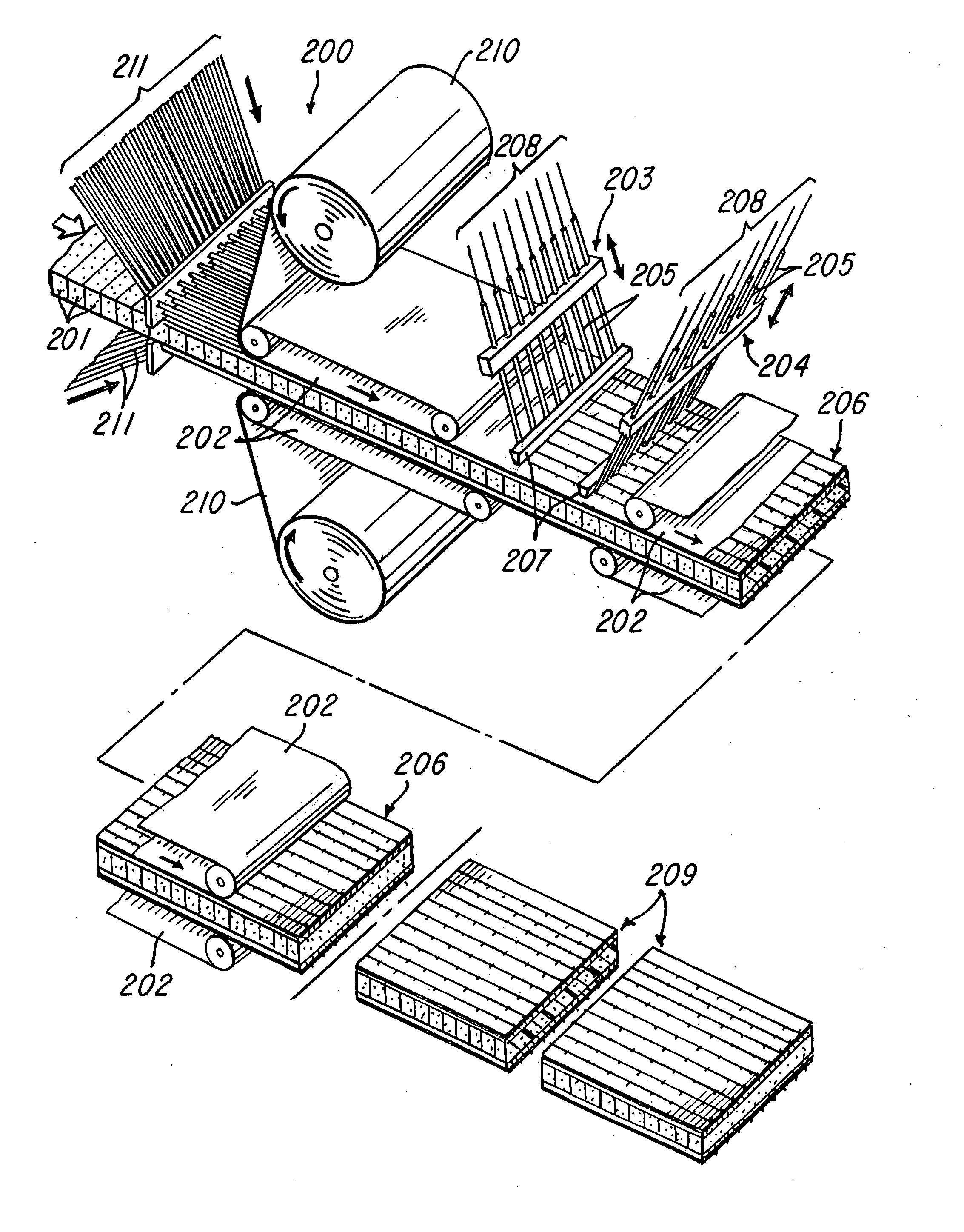
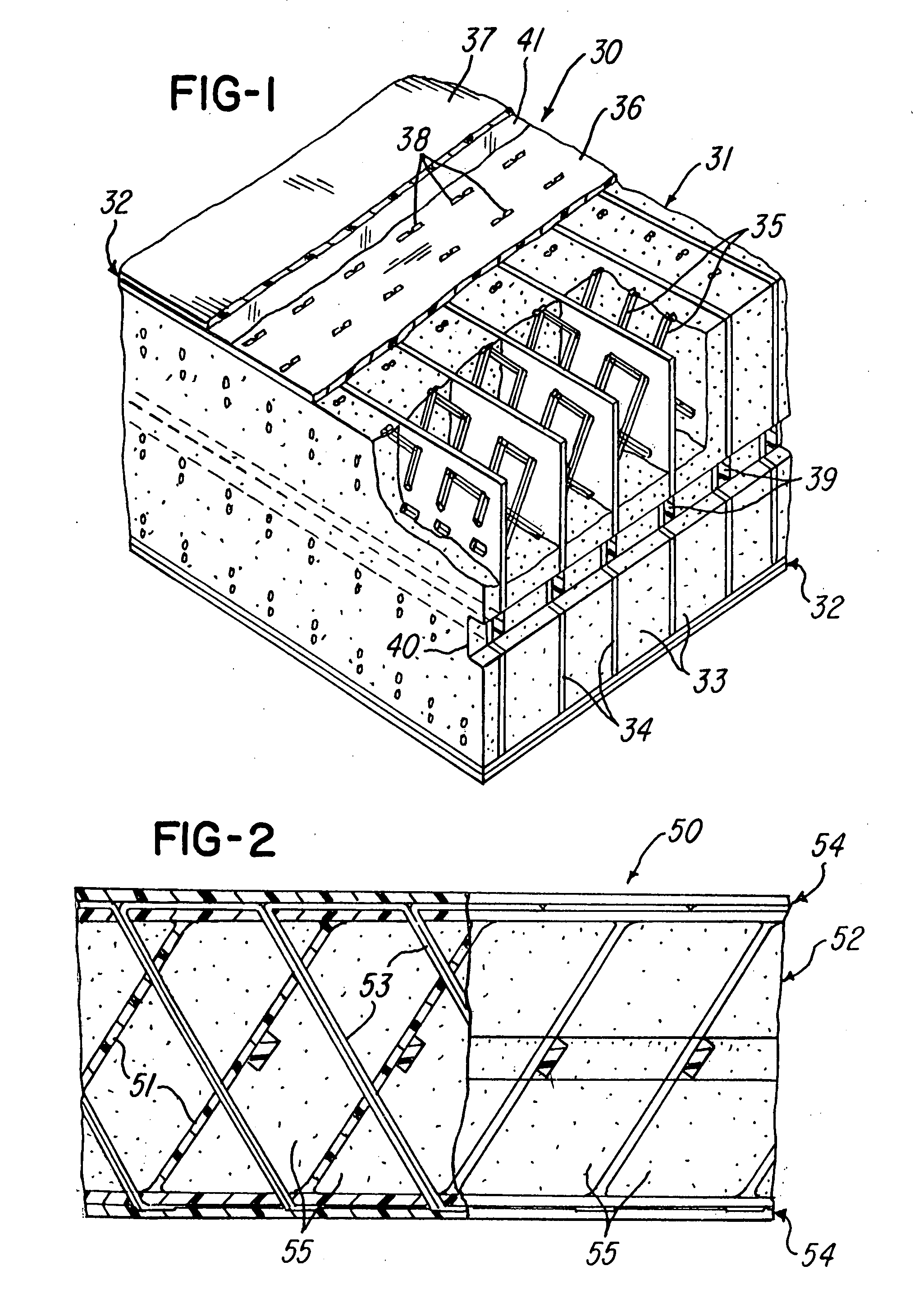
[0081]FIG. 1 illustrates a structural composite sandwich panel 30 which may be used, for example, as the floor of a highway truck cab, the hull or transom of a boat, the roof of a factory building, or as a vehicular or pedestrian bridge deck. Panel 30 comprises a fiber reinforced closed cell plastic foam core 31 and opposing fiber reinforced skins 32. Foam core 31 comprises a plurality of foam strips 33, whose structural properties are insufficient to resist loads in the core which would correspond with loads for which skins 32 are designed.

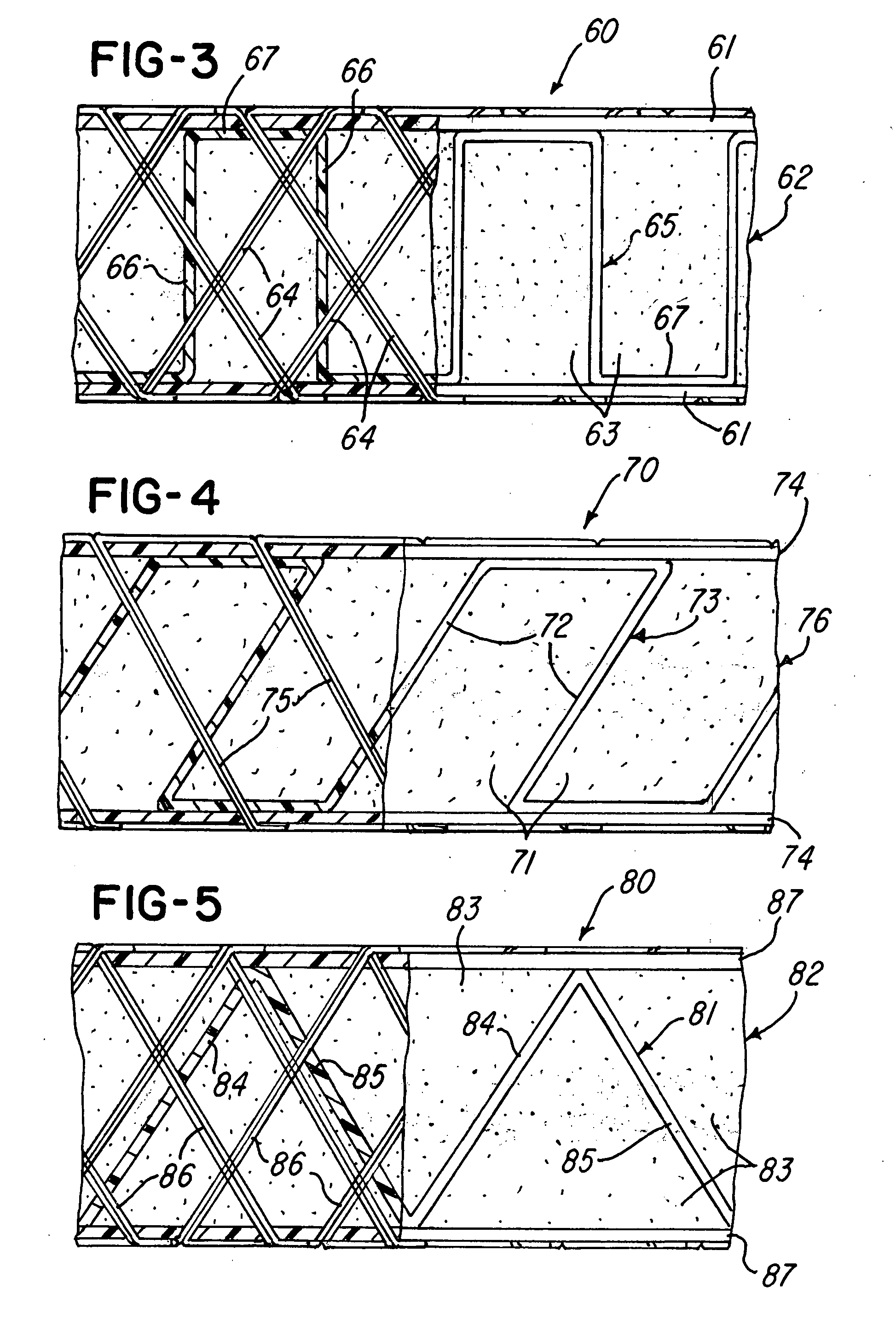
[0082]The core reinforcing fibers, which are selected to impart the required structural properties to the core, are of fiberglass or carbon fiber or other reinforcing fibers. In one direction, the reinforcing fibers comprise a plurality of parallel sheets or webs 34 of porous, fibrous fabric or mat which extend between the faces of the core 31 and which have been adhesively attached to one face of each foam strip 33 while maintaining substantial ...


PUM

PropertyMeasurementUnit
Pressureaaaaaaaaaa
Angleaaaaaaaaaa
Lengthaaaaaaaaaa

Abstract

A fiber reinforced core panel is formed from strips of plastics foam helically wound with layers of rovings to form webs which may extend in a wave pattern or may intersect transverse webs. Hollow tubes may replace foam strips. Axial rovings cooperate with overlying helically wound rovings to form a beam or a column. Wound roving patterns may vary along strips for structural efficiency. Wound strips may alternate with spaced strips, and spacers between the strips enhance web buckling strength. Continuously wound rovings between spaced strips permit folding to form panels with reinforced edges. Continuously wound strips are helically wrapped to form annular structures, and composite panels may combine both thermoset and thermoplastic resins. Continuously wound strips or strip sections may be continuously fed either longitudinally or laterally into molding apparatus which may receive skin materials to form reinforced composite panels.

Description

RELATED APPLICATIONS[0001]This application is a continuation-in-part of application Ser. No. 10 / 810,298, filed Mar. 27, 2004, which is a continuation-in-part of application Ser. No. 09 / 749,064, filed Dec. 27, 2000, and claims the benefit of provisional application Ser. No. 60 / 857,593, filed Nov. 9, 2006.U.S. GOVERNMENT RIGHTS[0002]This invention was made with U.S. Government support under US Air Force Contract No. F29601-02-C-0169 and under Contracts, F33615-99-C-3217, F33615-00-C-3018, F42650-03-C-0029, FA8201-06-C-0091, US Navy Contract N00167-99-C-0042 and NASA Contract NNC04CA18C. The Federal Government has certain rights in the invention.FIELD OF THE INVENTION[0003]This invention relates to sandwich panel composite structures comprising fiber reinforced low density cellular material, resin, fibrous and non-fibrous skin reinforcements, and in particular to improved structural configurations, improved methods of resin infusion and methods of production.BACKGROUND OF THE INVENTION...

Claims


Application Information

Patent Timeline
IPC IPC(8): B32B3/26B32B38/00B32B7/03
CPCB29C44/1285B29C44/569B29C70/083B29C70/24B29C70/504Y10T156/1075E04C2/243E04C2/246B32B5/12B32B7/005Y10T428/24132B29C70/865Y10T428/24996Y10T428/249982Y10T428/249981Y10T428/249953B32B7/03
Inventor DAY, STEPHEN W.CAMPBELL, G. SCOTTTILTON, DANNY E.STOLL, FREDERICKSHEPPARD, MICHAELBANERJEE, ROBIN
Owner METYX USA INC
Why Eureka
Try Eureka