Apparatus and method for measuring depth-of-interaction using light dispersion and positron emission tomography using the same

Active Publication Date: 2010-10-28
SEOUL NAT UNIV R&DB FOUND
View PDF7 Cites 16 Cited by
  • Summary
  • Abstract
  • Description
  • Claims
  • Application Information

AI Technical Summary

Benefits of technology

[0015]Accordingly, the present invention has been made in view of the above problems occurring in the prior art, and it is an object of the present invention to provide an apparatus and method for measuring a DOI and a PET using the same, which are capable of im

Problems solved by technology

This method is, however, disadvantageous in that a reduction in the size of components is limited and the cost is increased because of an increase in the number of detectors and electronic measuring instruments.
If the DOI information is unknown, a PET apparatus will have a significant error in determining a position where gamma rays has been generated because of the parallax errors in the peripheral field of view, inevitably resulting in a degraded spatial resolution.
However, this method is disadvantageous in that it provides only discrete DOI information, which is limited by the number of layers.
Light

Method used


Image

  • Apparatus and method for measuring depth-of-interaction using light dispersion and positron emission tomography using the same
  • Apparatus and method for measuring depth-of-interaction using light dispersion and positron emission tomography using the same
  • Apparatus and method for measuring depth-of-interaction using light dispersion and positron emission tomography using the same

Examples


first embodiment

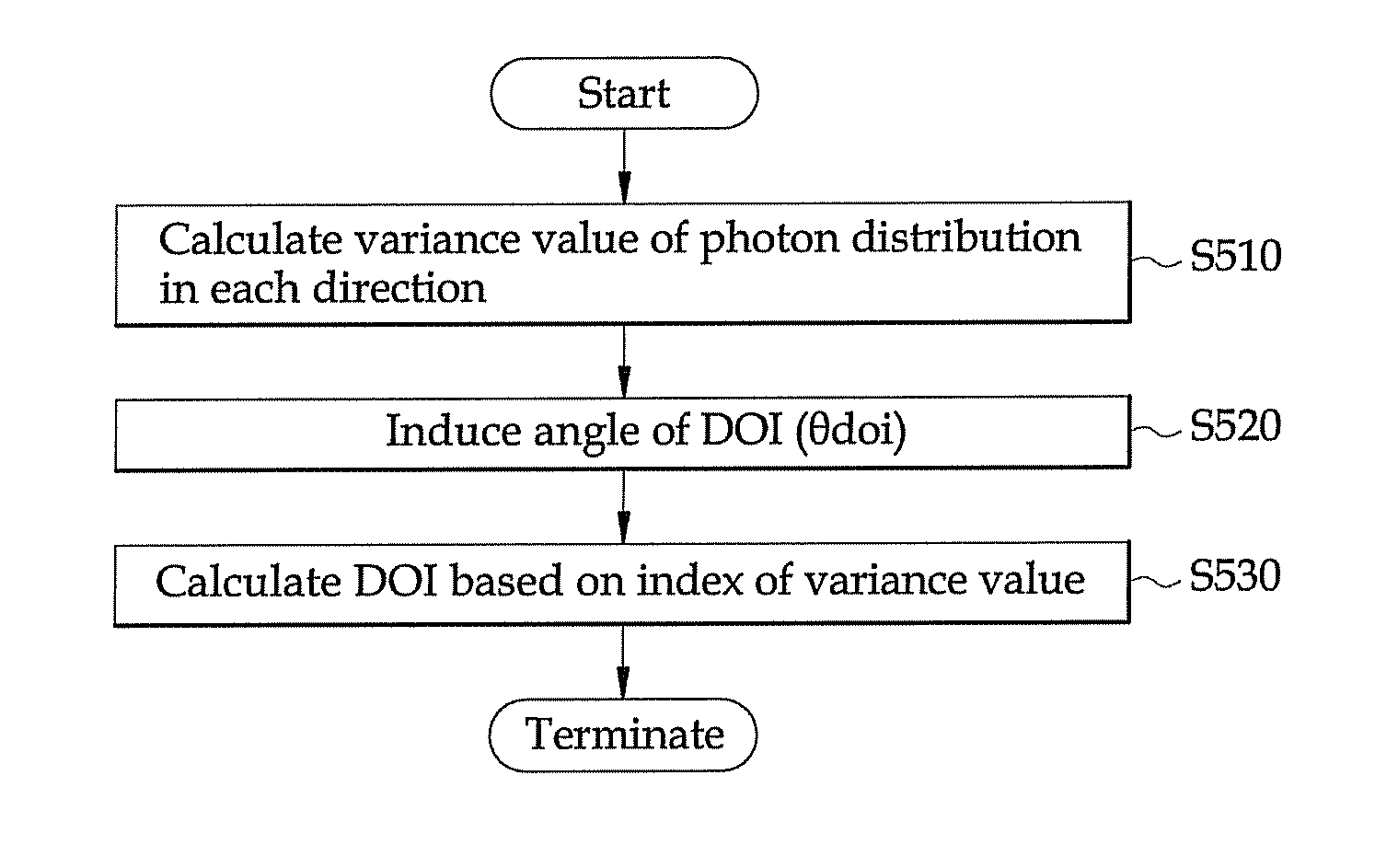
[0094]A method of measuring a DOI according to the first embodiment is described below. The method is described below with reference to FIG. 4.

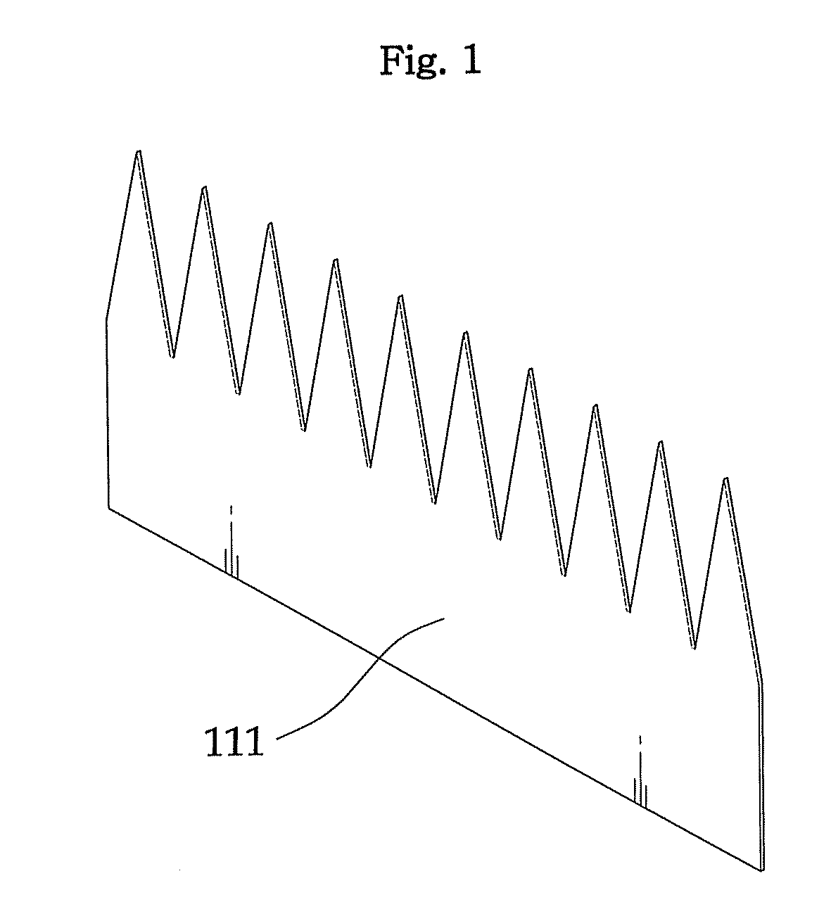
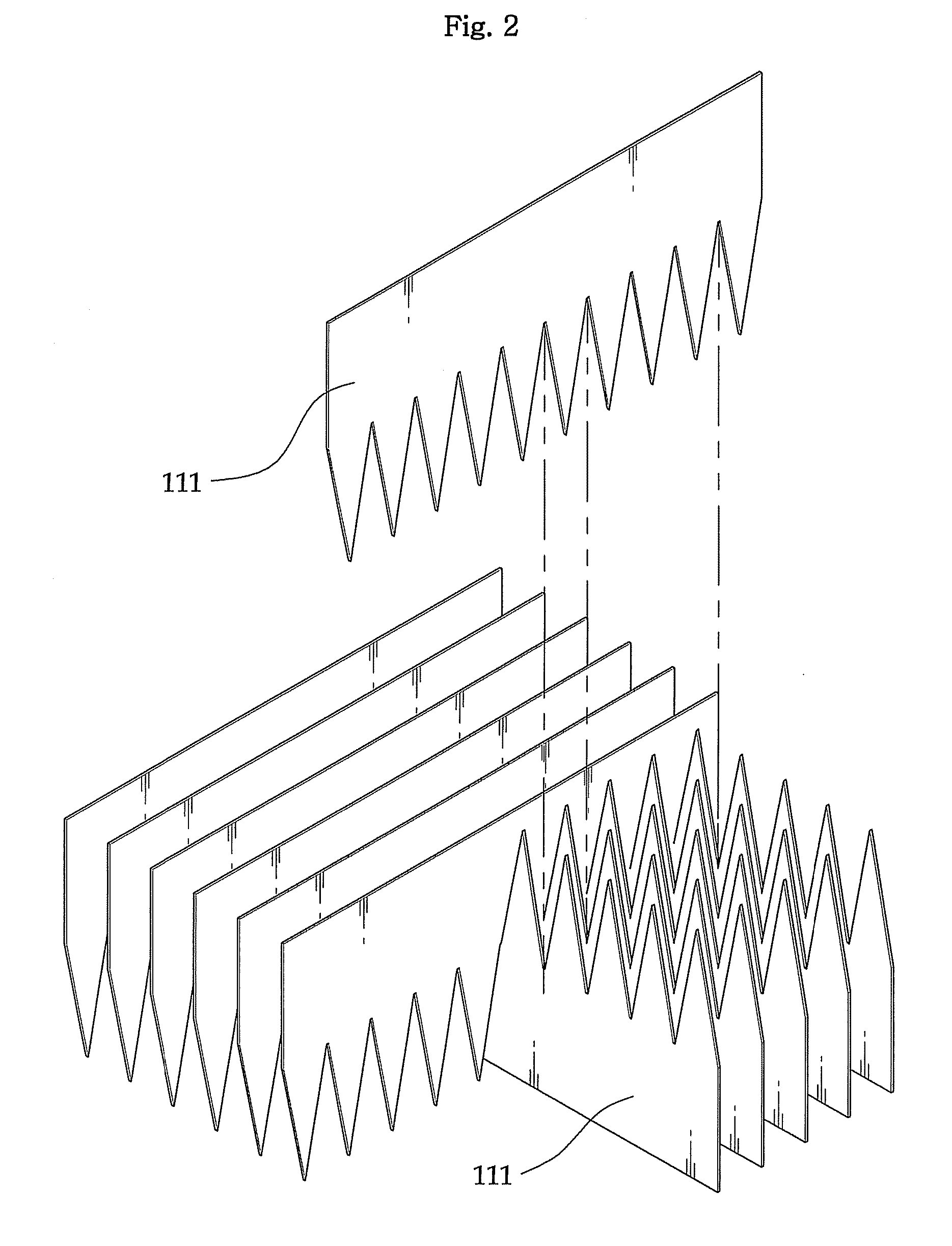
[0095]The reflective films are inserted into and attached to the rectangular parallelepiped crystals 110. Here, one direction is assumed to be an x axis, and the triangular tooth films 111 oriented toward the upper part are attached to the rectangular parallelepiped crystals 110. The other direction at a right angle to the one direction is assumed to be a y axis, and the triangular tooth films 111 oriented toward the lower part are attached to the rectangular parallelepiped crystals 110.

[0096]Scintillation light generated at a position having a shallow DOI (that is, from an upper portion distant from the position-sensitive PMT 20) is spread only in the y-axis direction, and so the number of photons detected in the x-axis direction will be small. Accordingly, the method of measuring an unknown DOI in accordance with such a principle is perform...

second embodiment

[0108]A method of measuring a DOI according to the second embodiment is described below. The method is described with reference to FIG. 7. The reflective films are inserted into and attached to the rectangular parallelepiped crystals 110. One direction is assumed to be an x axis, and the gradient films 112 having a transparent top surface are attached to the rectangular parallelepiped crystals 110. The other direction at a right angle to the one direction is assumed to be a y axis, and the gradient films 112 having a transparent bottom surface are attached to the rectangular parallelepiped crystals 110.

[0109]Scintillation light generated at a position having a shallow DOI (that is, from an upper portion distant from the position-sensitive PMT 20) is spread only in the y-axis direction, and so the number of photons detected in the x-axis direction will be small. To the contrary, scintillation light generated at a position having a deep DOI (that is, from a lower portion close to the ...

third embodiment

[0110]A method of measuring a DOI according to the third embodiment is described below. The method is described with reference to FIG. 10. The reflective films are inserted into and attached to the triangle pole-shaped crystal 120, and an angle formed by the reflective films is 60°.

[0111]When scintillation light is generated, a large number of photons are detected at positions having a shallow DOI along the diamond-shaped films 123, a large number of photons are detected at positions having a DOI half the length of the crystals along the triangular films 121, and a large number of photons are detected at positions having a deep DOI along the diamond-shaped films 123. Accordingly, the method of measuring an unknown DOI in accordance with the principle is the same as that of the first embodiment.

[0112]As described above, the present invention has an advantage in that it can improve and maintain the spatial resolution through the arrangement of the reflective films, while using the cry...


PUM


Abstract

The present invention provides an apparatus for measuring a Depth-Of-Interaction (DOI), comprising a crystal layer 10 of a mono layer in which a plurality of crystals for absorbing gamma rays are consecutively arranged, scintillation light detectors disposed at one end of the crystals and configured to detect scintillation light emitted from the crystal layer 10 by the gamma rays, change means included in the crystals and configured to linearly change transmittance in a length direction of the crystals, and a control unit 30 configured to calculate the DOI in the crystal layer 10 on a basis of the first output signal and the second output signal. The scintillation light detector outputs the first output signal in one direction and the second output signal in a direction at a right angle to the one direction.

Description

BACKGROUND OF THE INVENTION[0001]1. Field of the Invention[0002]The present invention relates to an apparatus and method for measuring a Depth-Of-Interaction (hereinafter referred to as a ‘DOI’) which is capable of improving the spatial resolution in a Positron Emission Tomography (hereinafter referred to as a ‘PET’). More particularly, the present invention relates to an apparatus and method for measuring a DOI using a light dispersion property within the crystal layer of a mono layer into which reflective films are inserted, and a PET using the same.[0003]2. Background of the Related Art[0004]The PET (Positron Emission Tomography) is a tomography using radioactive rays, such as X-ray Computerized Tomography (CT) tomography and a Single Photon Emission Computerized Tomography (SPECT).[0005]The PET is typically a technique for imaging a distribution of foreign substances within the body by injecting a radioactive sample, emitting positrons, into an organism through an intravenous in...

Claims


Application Information

Patent Timeline
IPC IPC(8): G12B13/00G01T1/208G01T1/166
CPCG01T1/2002A61B6/037G01T1/202A61B6/00
Inventor LEE, JAE SUNGITO, MIKIKOHONG, SEONG JONG
Owner SEOUL NAT UNIV R&DB FOUND
Why Eureka
Try Eureka