
Electricity storage and recovery system

a technology of electricity storage and recovery system, applied in the direction of electric generator control, machines/engines, mechanical equipment, etc., can solve the problems of limited construction sites, low conversion efficiency, and high energy density, and achieve the effect of reducing the solubility of high-pressure gas and low construction cos

Inactive Publication Date: 2010-10-28
HOULY
View PDF9 Cites 19 Cited by
  • Summary
  • Abstract
  • Description
  • Claims
  • Application Information

AI Technical Summary

Benefits of technology

[0003]A major purpose of the present invention therefore is to provide a low-cost and simple electrical energy storage and recovery system that is not limited to specific construction sites and that the electricity storage and recovery is more economical.
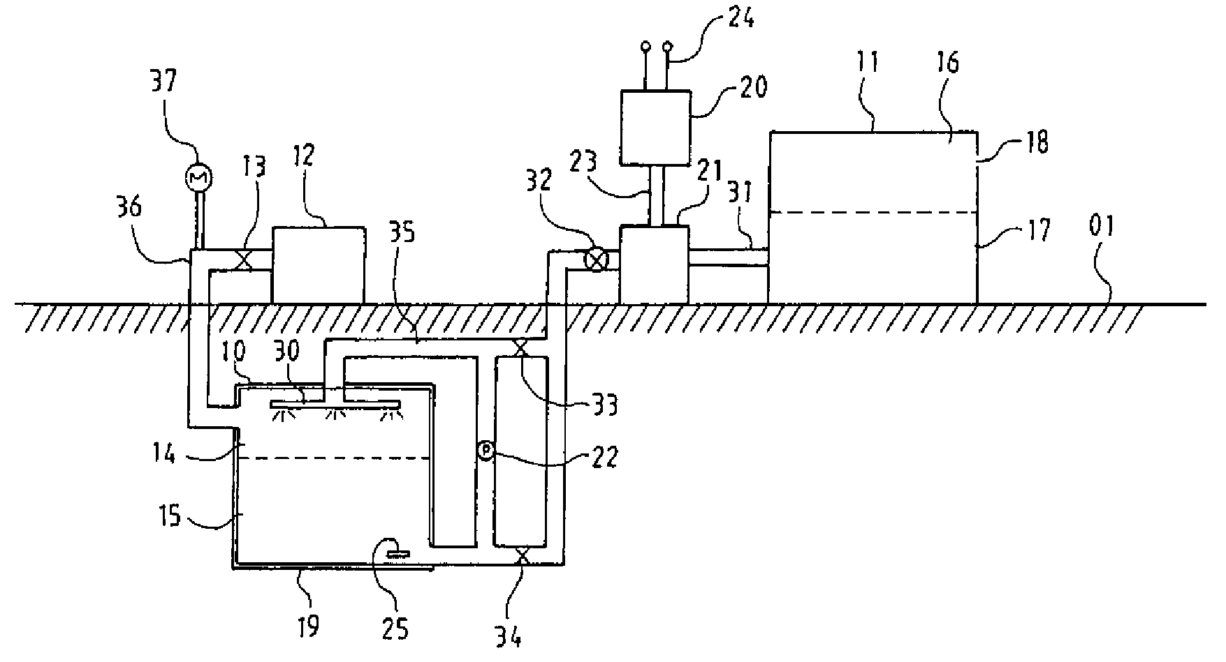
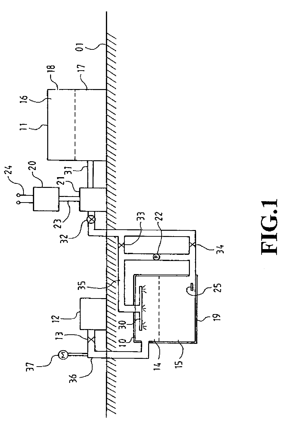
[0006]According to the present invention, when the normal-pressure fluid is pumped into the high-pressure tank, the temperature of the high-pressure gas would rise as it is compressed. Therefore, in an embodiment of the present invention, the normal-pressure fluid is sprayed from the top of the high-pressure tank by a sprayer so as to reduce the temperature of the high-temperature gas and also to store the heat energy in the fluid. If such heat exchange is not enough, the high-pressure fluid is drawn from the bottom of the high-pressure tank to the sprayer through an additional pump so as to reduce the gas / fluid temperature difference as much as possible.
[0008]According to the present invention, as the high-pressure tank needs to withstand a high pressure, the high-pressure tank could be built underground so that a less strong and thereby less expensive material could be used for the construction of the high-pressure tank. The high-pressure tank could be further wrapped by heat insulation material to reduce energy loss.
[0009]According to the present invention, when the high-pressure fluid flows out of the high-pressure tank and the high-pressure gas cools down as it expands, the aforementioned additional pump draws the high-pressure fluid from the bottom of the high-pressure tank to the sprayer for additional heat exchange so as to reduce the gas / fluid temperature difference as much as possible. This is also the means to convert the heat energy of the fluid to gas pressure, and then into to electrical energy.
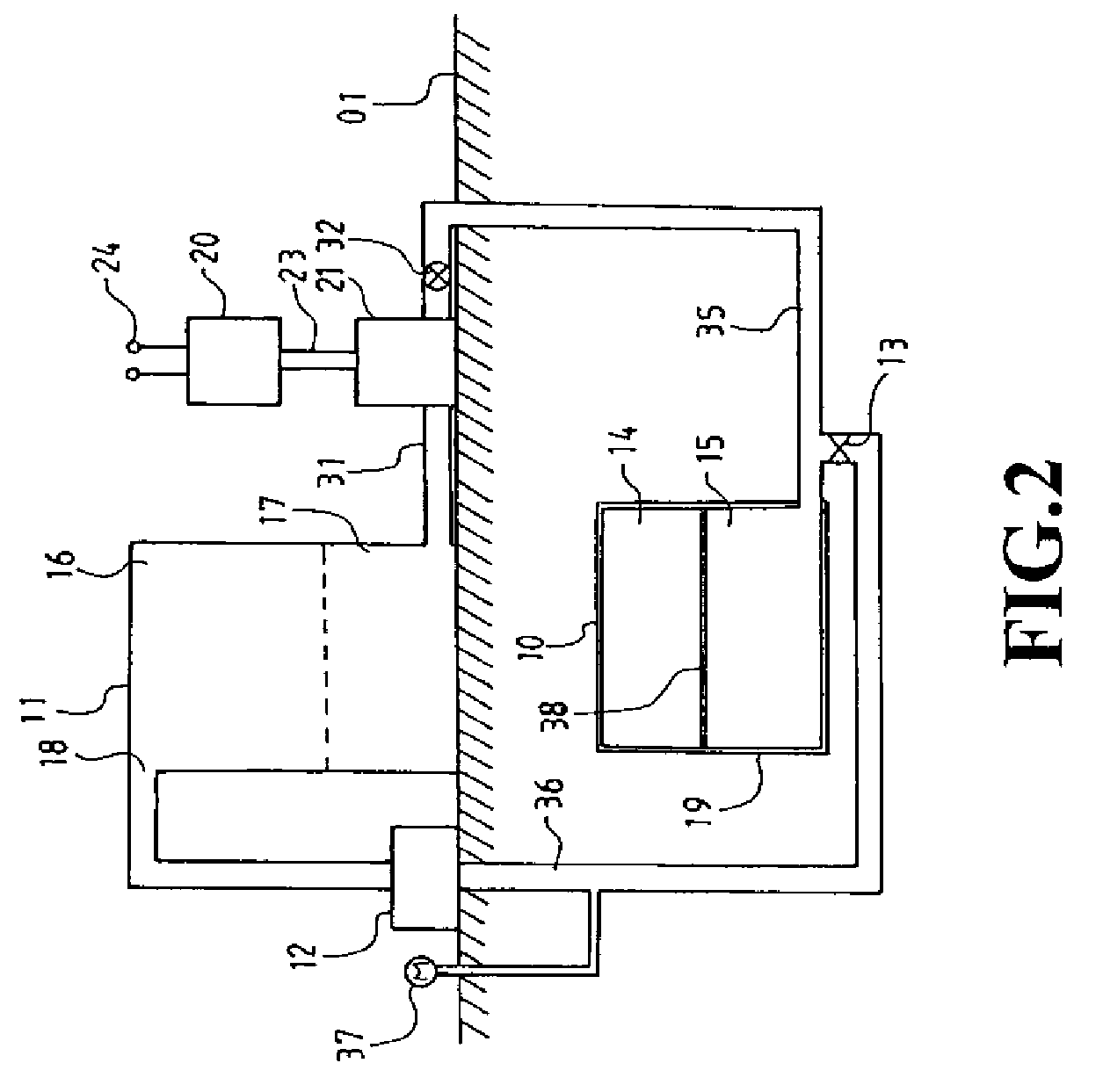
[0011]According to the present invention, the electrical energy storage and conversion device could omit the means of heat exchange for even lower construction cost and simply employs a thermal baffle inside the high-pressure tank to separate the high-pressure gas and fluid. This could reduce the solubility of the high-pressure gas in the high-pressure fluid.

Problems solved by technology

The former has high energy density but low conversion efficiency.
There are limited construction sites and huge cost is involved, in addition to the profound impact to the ecosystem.

Method used


Image

  • Electricity storage and recovery system
  • Electricity storage and recovery system
  • Electricity storage and recovery system

Examples


Embodiment Construction

[0016]The following descriptions are exemplary embodiments only, and are not intended to limit the scope, applicability or configuration of the invention in any way. Rather, the following description provides a convenient illustration for implementing exemplary embodiments of the invention. Various changes to the described embodiments may be made in the function and arrangement of the elements described without departing from the scope of the invention as set forth in the appended claims.

[0017]As shown in FIG. 1, an electrical electricity storage and recovery system according to an embodiment of the present invention mainly contains a high-pressure tank 10 where high-pressure gas 14 and high-pressure fluid 15 (i.e., working fluid) such as water, saline water, or oil, are stored inside, and an ordinary-pressure tank 11 where normal-pressure gas 16 and normal-pressure fluid 17 identical to the high-pressure fluid 15 are stored inside. If air is used as the normal-pressure gas 16, the ...


PUM


Abstract

The electricity storage and recovery system. At first, injects high-pressure gas in a high-pressure tank and then, the normal-pressure fluid from a normal-pressure tank is pumped into the high-pressure tank by a motor-driven pump so that the electrical energy is converted to high-pressure potential energy of the fluid stored inside the high-pressure tank. To recover the potential energy back to electrical energy, the high-pressure fluid flows from the bottom of the high-pressure tank to the normal-pressure tank through a turbine. The turbine in turn drives a generator to produce electricity. The pump and the turbine are of a same device running in opposite directions. The motor and the generator are also of a same device running in opposite directions.

Description

(a) TECHNICAL FIELD OF THE INVENTION[0001]The present invention generally relates to devices for electricity storage and recovery system, and more particularly to store electricity in off-peak hour then recover it during the period of peak demand.(b) DESCRIPTION OF THE PRIOR ART[0002]Electricity consumption has high peak periods and off peak periods and therefore storing electrical energy during off peak periods and retrieving the stored energy during high peak periods is a common practice. Currently, there are two major approaches for storing large-volume electrical energy. One is compressed air energy storage (CAES) and the other one is pumped hydro storage. The former has high energy density but low conversion efficiency. Usually, to convert the stored energy back to electrical energy requires heating using fuel. For the latter, even though the recovery efficiency could reach 80%, the construction of a huge dam is required. There are limited construction sites and huge cost is in...

Claims


Application Information

Patent Timeline
IPC IPC(8): H02K7/18F15B1/027
CPCF15B1/02F01D15/10
Inventor LIU, KUO-SHEN
Owner HOULY
Learn More