Solid electrolytic capacitor

a solid electrolytic capacitor and capacitor technology, applied in the direction of liquid electrolytic capacitors, fixed capacitors, fixed capacitor details, etc., can solve the problems of conductive adhesive material cracking, low reliability, thermo cycle, etc., and achieve good esr, less deterioration of esr, and high bonding strength

Inactive Publication Date: 2010-10-28
SANYO ELECTRIC CO LTD
View PDF5 Cites 8 Cited by
  • Summary
  • Abstract
  • Description
  • Claims
  • Application Information

AI Technical Summary

Benefits of technology

[0012]An object of the present invention is to provide a solid electrolytic capacitor free from formation of bubbles in a conductive adhesive material, achieving high bonding strength between cathode lead frame 94 and capacitor element 91 in an early stage, good ESR, less deterioration of ESR even after heat cycle tests, and improved reliability, and capable of preventing lowering in mechanical strength, deterioration of moisture-resistance characteristics, poor appearance, and increase in cost.

Problems solved by technology

Therefore, a crack may be produced in conductive adhesive material 95 after such electronic devices as a portable telephone or a computer containing the solid electrolytic capacitor have been marketed.
Thermo cycle tests for testing change over time revealed low reliability, because ESR was poor due to production of a crack in conductive adhesive material 95.
If external force is applied to that portion, that portion may be deformed and broken (that is, mechanical strength may become lower).
Further, as a degree of protrusion is greater, protruding portion 95A is exposed through molded resin 92, which in turn gives rise to such problems as poor moisture-resistance characteristics or poor appearance.
In order to suppress the degree of protrusion to a prescribed level or lower, process management becomes complicated and hence cost is increased.

Method used


Image

  • Solid electrolytic capacitor
  • Solid electrolytic capacitor
  • Solid electrolytic capacitor

Examples


Embodiment Construction

[0029]An embodiment of the present invention will be described hereinafter with reference to the drawings.

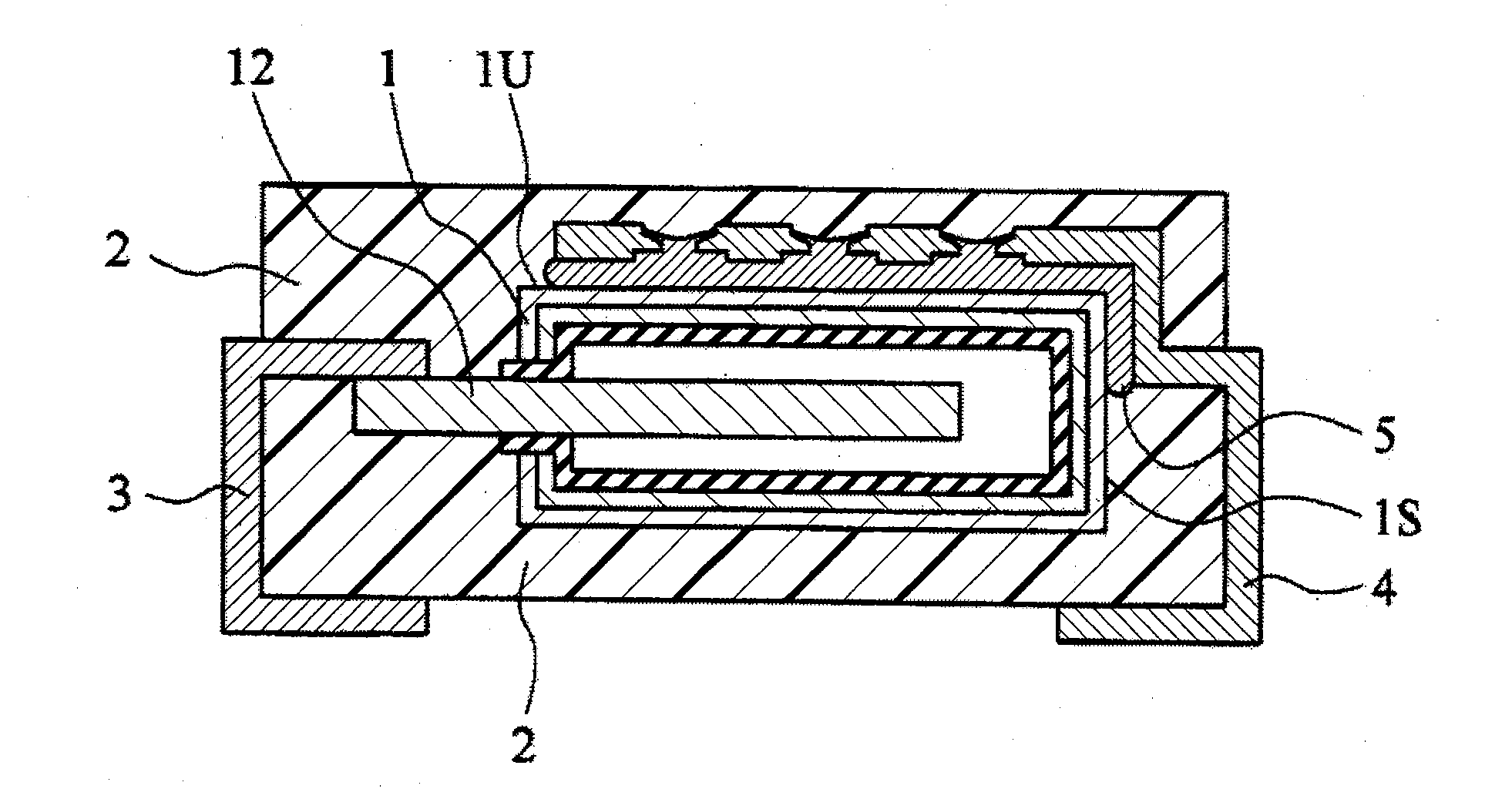
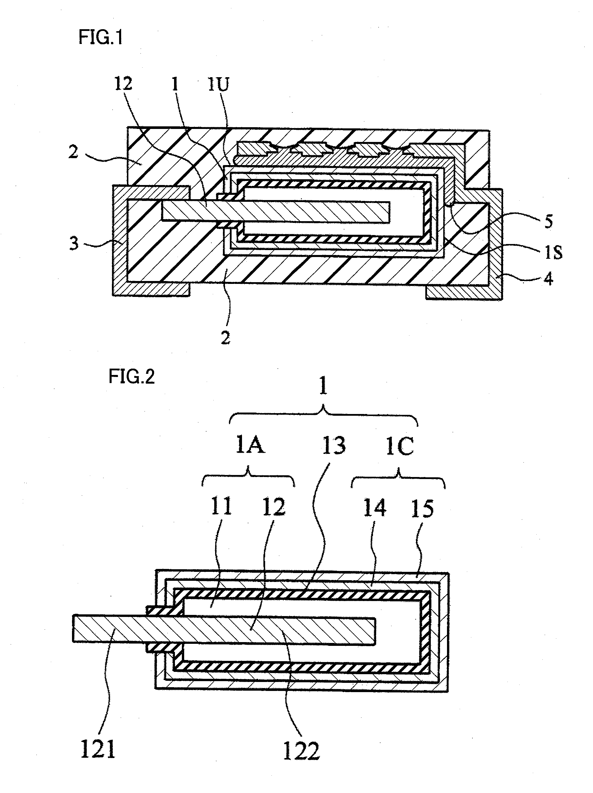
[0030]FIG. 1 shows a cross-sectional view of a solid electrolytic capacitor according to an embodiment of the present invention. The solid electrolytic capacitor includes a capacitor element 1, an anode lead frame 3, a cathode lead frame 4, and a molded resin 2. As shown in FIG. 2, capacitor element 1 is constituted of an anode element 11 on which an anode lead member 12 is erected, a dielectric film 13 formed on an outer peripheral surface of anode element 11, a solid electrolyte layer 14 formed on dielectric film 13, and a cathode draw-out layer 15 formed on solid electrolyte layer 14.

[0031]Anode element 11 is formed of, a sintered object of a valve metal (such as tantalum, niobium, titanium, and aluminum).

[0032]Anode lead member 12 has an anode lead draw-out portion 121 projecting from an outer peripheral surface of anode element 11 and an anode lead buried portion 122 buried...


PUM


Abstract

A solid electrolytic capacitor includes a capacitor element having an anode portion, a dielectric film and a cathode portion, an anode lead frame, a cathode lead frame, and a molded resin for covering at least a part of the anode and cathode lead frames and the capacitor element. In a cathode lead frame opposed portion opposed to the capacitor element with a conductive adhesive material being interposed is provided with a through hole having a narrowed portion smaller in diameter than other portions between a capacitor-element-side opening portion and a molded-resin-side opening portion, and the conductive adhesive material is formed in the through hole.

Description

BACKGROUND OF THE INVENTION[0001]1. Field of the Invention[0002]The present invention relates to a solid electrolytic capacitor formed by connecting a capacitor element to a cathode lead frame.[0003]2. Description of the Background Art[0004]A solid electrolytic capacitor having a structure as shown in FIG. 7 has been known as a conventional solid electrolytic capacitor. This solid electrolytic capacitor includes a capacitor element 91, an anode lead frame 93, a cathode lead frame 94, and a molded resin 92. As shown in FIG. 8, capacitor element 91 is constituted of an anode element 911 on which an anode lead member 912 is erected, a dielectric film 913 formed on an outer peripheral surface of anode element 911, a solid electrolyte layer 914 formed on dielectric film 913, and a cathode draw-out layer 915 formed on solid electrolyte layer 914. Anode element 911 is formed of a sintered object of a valve metal (such as tantalum, niobium, titanium, and aluminum).[0005]Anode lead member 91...

Claims


Application Information

Patent Timeline
Patent Type & Authority Applications(United States)
IPC IPC(8): H01G9/15H01G9/048H01G9/012
CPCH01G9/012H01G9/15H01G9/10
Inventor FURUZAWA, ATSUSHIIZU, HIROAKI
Owner SANYO ELECTRIC CO LTD
Why Eureka
Try Eureka