
Capacitor microphone and impedance converter therefor

Active Publication Date: 2010-10-28
AUDIO-TECHNICA
View PDF4 Cites 2 Cited by
  • Summary
  • Abstract
  • Description
  • Claims
  • Application Information

AI Technical Summary

Benefits of technology

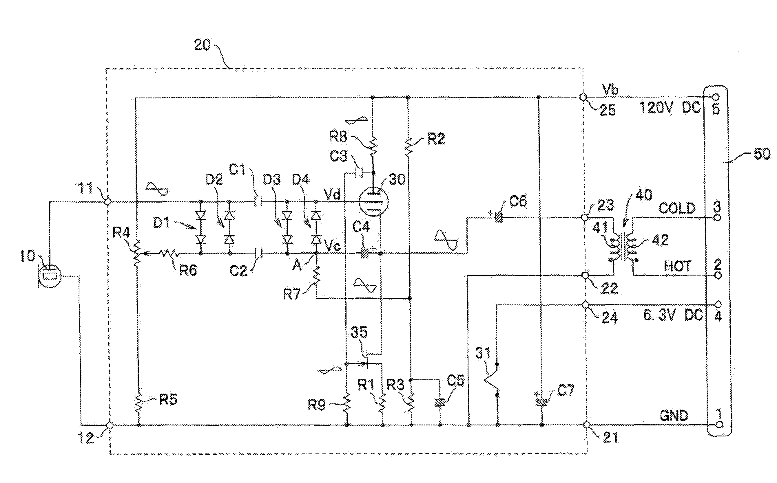
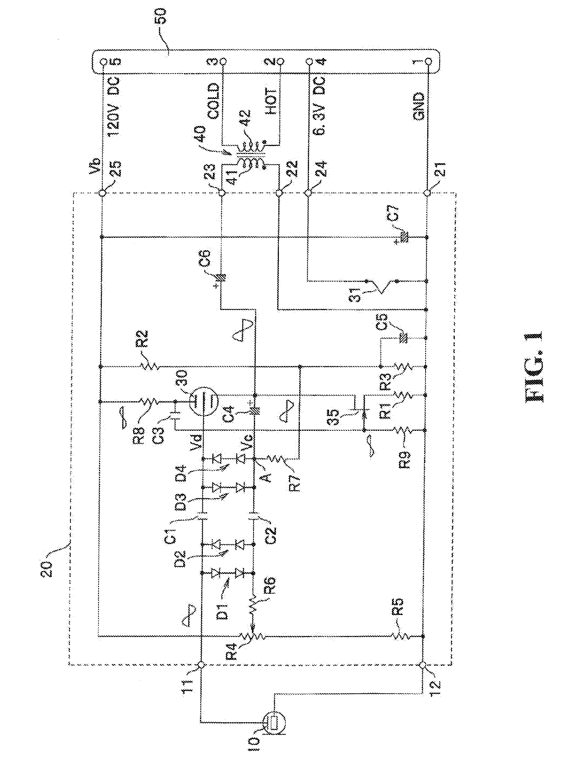
[0015]In the capacitor microphone and the impedance converter therefor, the vacuum tube as the impedance conversion element and the FET are in cascade connection. Thus, the FET can serve as a constant current diode and the plate current of the vacuum tube can be more stable.
[0016]Use of the FET instead of a vacuum tube as an element that defines a plate current of a vacuum tube used as an impedance conversion element can prevent dielectric breakdown as a result of a large potential difference between the cathode and the heater as in the case where another vacuum tube is used as the element that defines a plate current. Thus, noise due to the dielectric breakdown can be prevented. Further, because, instead of a vacuum tube, the FET is used as an element that defines a plate current of the vacuum tube used as an impedance conversion element, power consumption can be reduced as much as the power required for heating another vacuum tube.

Problems solved by technology

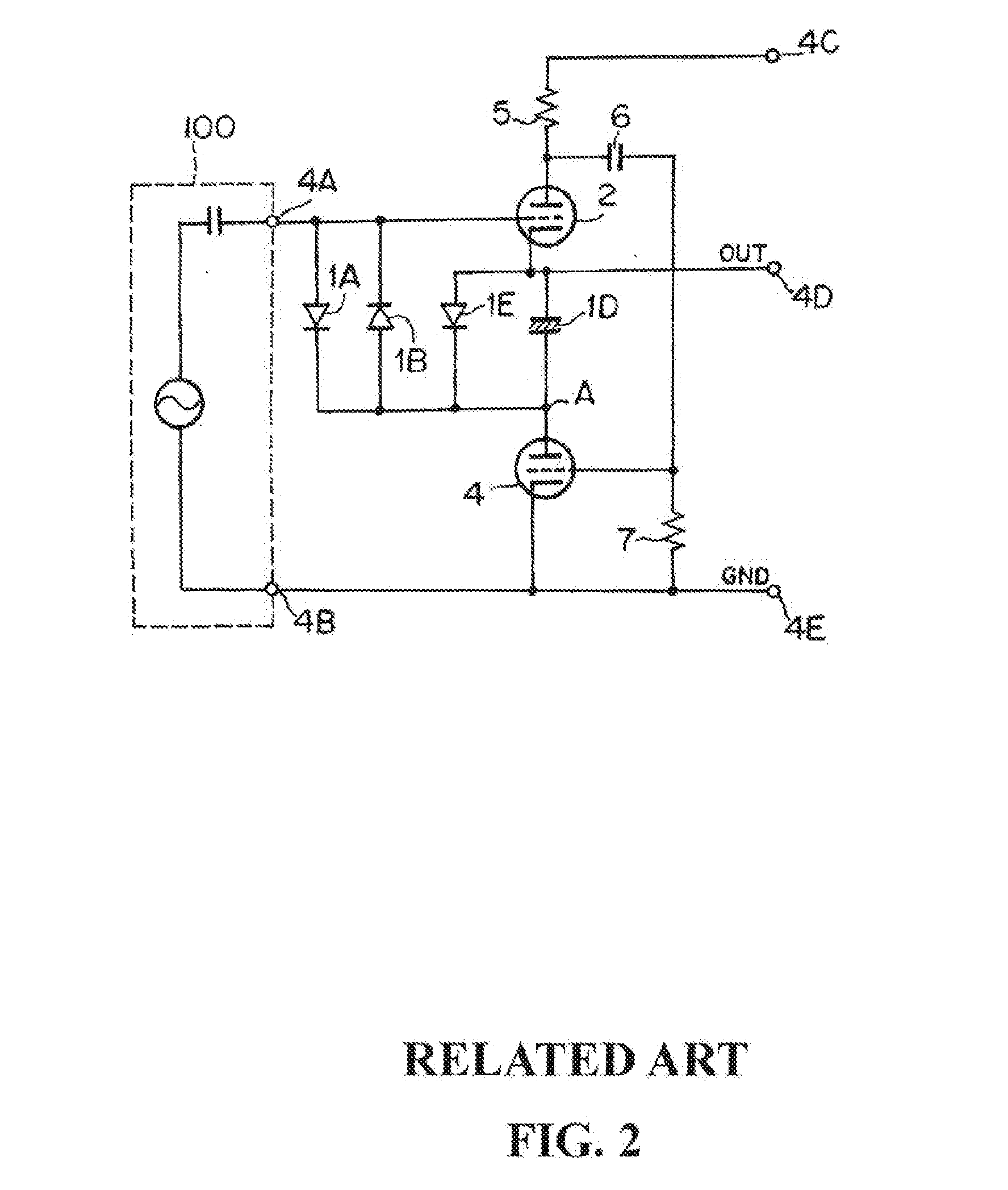
Unfortunately, the amplifier tubes 2 and 4 each formed of a vacuum tube have highly variable characteristics, and the potential of the output signal extracted from the output terminal 4D is difficult to be maintained at a constant level.
Further, noise may be produced as a potential difference between the cathode and the heater of the first amplifier tube 2 becomes large to cause dielectric breakdown therebetween.
Thus, power consumption is high.

Method used


Image

  • Capacitor microphone and impedance converter therefor
  • Capacitor microphone and impedance converter therefor
  • Capacitor microphone and impedance converter therefor

Examples


Embodiment Construction

[0019]Embodiments of a capacitor microphone and an impedance converter therefor according to the present invention are described below with reference to a drawing.

[0020]FIG. 1 shows a capacitor microphone unit 10, and this impedance converter 20 formed in a block defined with the dotted line. Two electrodes forming the capacitor microphone unit 10 are connected to an input terminal 11 and a ground input terminal 12 of the impedance converter 20, respectively. An output signal from the capacitor microphone unit 10 received by the impedance converter 20 through the input terminal 11 is fed to the grid of a vacuum tube 30 via a coupling capacitor C1. The vacuum tube 30 is a triode and serves as an impedance conversion element. A high direct power-supply voltage (for example 120 V) Vb is applied via a supply terminal 25 of the impedance converter 20 to the plate of the vacuum tube 30 via a resistor R8.

[0021]The vacuum tube 30 is connected for cathode follower output and is in cascade co...


PUM


Abstract

An impedance converter for a capacitor microphone includes: a vacuum tube that receives an output signal from a capacitor microphone unit through a grid and with which the signal is output as an output from a cathode follower; an FET in cascade connection with the vacuum tube and that defines a current flowing in the vacuum tube; and a bias circuit that applies a bias voltage to the grid of the vacuum tube. The bias circuit includes: a first diode and a second diode that apply the bias voltage to the grid of the vacuum tube; the first diode and the second diode being connected in inverse parallel; and a bias resistor for applying the bias voltage at a constant level to the grid of the vacuum tube via the first diode or the second diode.

Description

BACKGROUND OF THE INVENTION[0001]1. Field of the Invention[0002]The present invention relates to a capacitor microphone and an impedance converter therefor. More specifically, the present invention relates to a capacitor microphone and an impedance converter therefor using a vacuum tube as an impedance converting element improved for stable operation and avoidance of sound quality degradation.[0003]2. Description of the Related Art[0004]Capacitor microphones have small effective capacitance and high output impedance. Thus, for an output signal from a capacitor microphone, high input impedance is required to assure frequency response at a low frequency domain, as well as at a high frequency domain or a mid-frequency domain. Upon feeding an output signal from a capacitor microphone to an amplifier through a cable and the like, the output impedance of the capacitor microphone needs to be lowered. Therefore, capacitor microphones incorporate an impedance converter having high input impe...

Claims


Application Information

Patent Timeline
IPC IPC(8): H04R3/00
CPCH04R3/00
Inventor AKINO, HIROSHI
Owner AUDIO-TECHNICA
Learn More