
Structural improvement of a canned motor pump

Active Publication Date: 2010-10-28
ASSOMA
View PDF1 Cites 35 Cited by
  • Summary
  • Abstract
  • Description
  • Claims
  • Application Information

AI Technical Summary

Benefits of technology

[0035]Therefore the primary object of the present invention is to provide a canned motor pump, wherein a cantilever shaft fixed at one shaft end being improved further, allowing intensity of a stationary shaft to satisfy requirements of all kinds, such as various shaft power and high rotational speed. In addition, a sealing function of a containment shell is improved to satisfy requirements of corrosion-resistance to all kinds of chemical fluid, due to the creative structure better satisfy requirement of structural intensity in high temperature applications.

Problems solved by technology

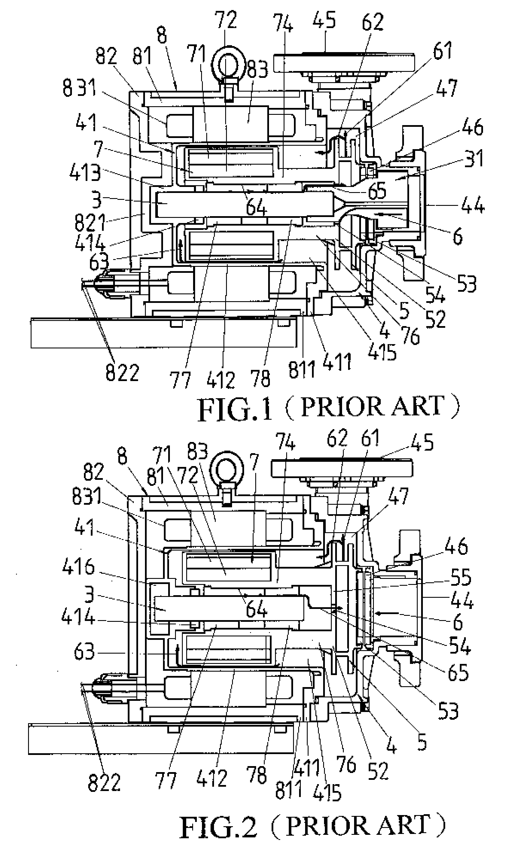
From the prior art as the stationary shaft 3 is supported by the plastic parts with lower structural stiffness, an issue of insufficient structural stiffness will be confronted with frequently, especially that if the temperature of transferred liquid goes up to 85° C. Furthermore, due to the differentials in thermal deformation between the plastic member and the ceramic member, and that will reduce the supporting force on the stationary shaft 3 a lot or increase deflection from fixed position of the stationary shaft 3.
Concluding from the operating requirements of the pump described above, the core issues that need to face with for the application of a high corrosive manufacturing process are:(1) The issue is the insufficient combining stiffness due to the differentials in thermal properties between the plastic material and the ceramic material;(2) The issue of decreased intensity of the plastic material under high temperature; and(3) The issue of increased centrifugal force when the operating speed exceeds the rated speed.
(1) For the insufficient combining stiffness between plastic and ceramic issue: many corrosion-resistance plastic materials do not have a good physical property to resist thermal deformation and therefore, cannot maintain a tight combination with the ceramic material. However, an additional reinforce structure will be needed.(2) For the structure stiffness of the plastic material issue: some plastic will be still provided with strong intensity when temperature increases, but their corrosion-resistance is insufficient. The intensity of many corrosion-resistance materials cannot compare with that of the ceramic material, especially that the intensity of material will be decreased significantly when temperature increases. Therefore, a brand new concept about the structure of shaft will be needed.)(3) For the centrifugal force of motor rotor at high speed issue: as the motor rotor is heavy in mass with a residual unbalance or an eccentric in radius, and the necessary gap in radius for lubrication between the hydraulic bearings and the stationary shaft will increase the centrifugal load of stationary shaft that is the load of centrifugal force on the stationary shaft could be calculated as the mass of motor rotor times the centrifugal acceleration of the rotation, and the centrifugal acceleration of rotation is calculated as the total eccentric radius of rotor times the angular velocity in square, the total eccentric radius is the eccentric radius of unbalance of rotor plus the eccentric radius of the hydraulic bearings. However, a higher stiffness of the stationary shaft and a lower mass of motor rotor will be needed.
Some of the wetting parts, like the flange of the containment shell, made of metal material is injected with plastic material; the plastic material used by the referred patent is engineering-grade plastic which is high temperature-resistant and is with high stiffness, but this material cannot withstand high corrosive fluid such as hydrofluoric acid.
Secondly, as the thickness of the column part of the containment shell is thin, the stiffness is insufficient to support the load of stationary shaft, which will easily cause the stationary shaft to be displaced or off-positioned.
However, the structure has good solution by using combining materials at the bottom of the containment shell and high temperature applications, but unable to solve structure stiffness issue at the column part of the containment shell and do not meet the requirement of high corrosion application also.
However, the structure is still unable to solve the combining stiffness issue and structure stiffness issue in high corrosion and high temperature applications.

Method used


Image

  • Structural improvement of a canned motor pump
  • Structural improvement of a canned motor pump
  • Structural improvement of a canned motor pump

Examples


Embodiment Construction

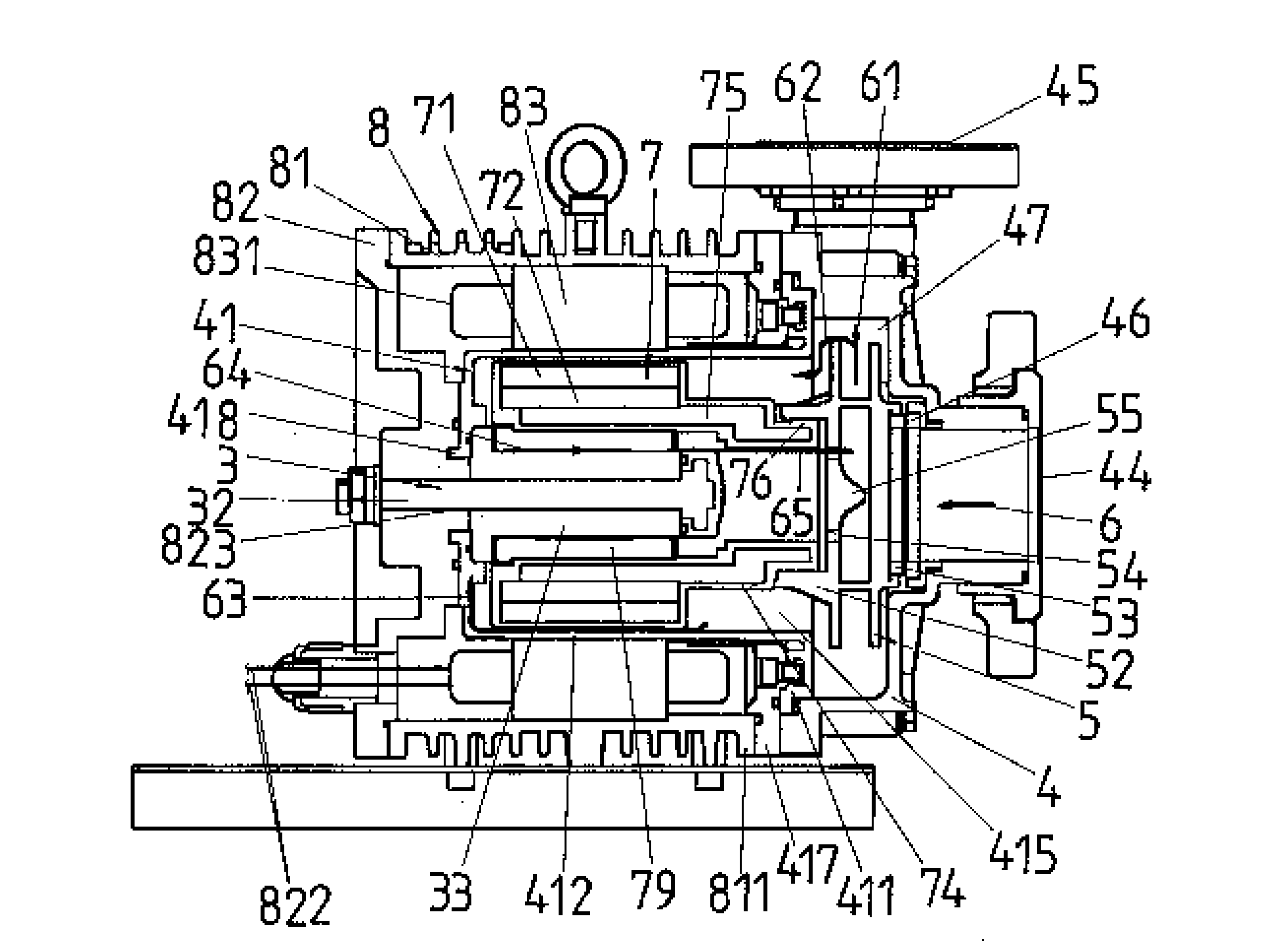
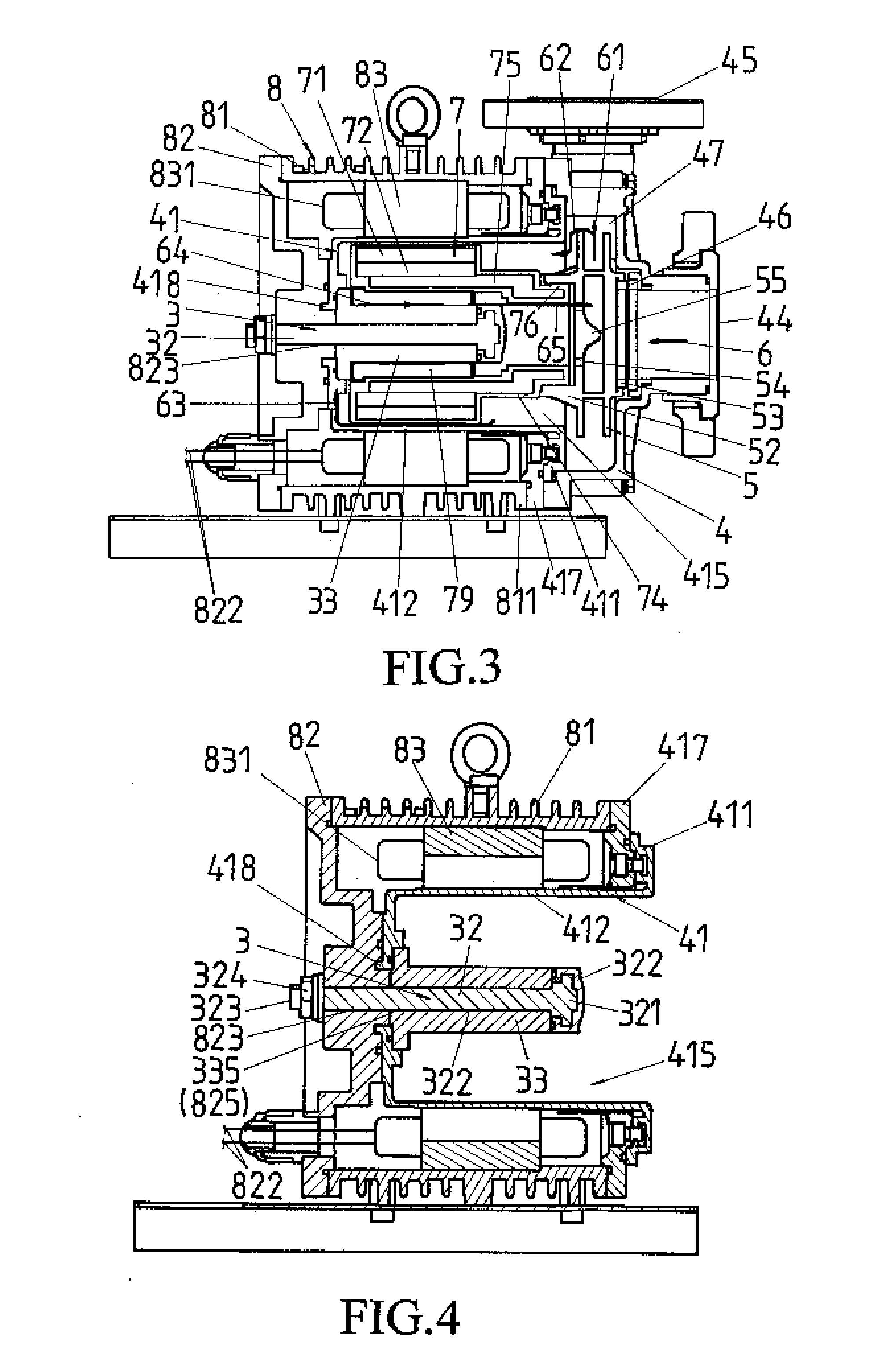
[0046]Referring to FIG. 3, a canned motor pump of the present invention is with a cantilever shaft and comprises a pump casing 4, an impeller 5 and a canned motor 8.

[0047]The pump casing 4 is provided with an inlet 44, an outlet 45 and a flow channel 47, which contains the impeller 5. An inlet thrust ring 46 is provided in an interior side of the pump casing 4 at the inlet 44 to couple with an impeller wear ring 53 at an inlet side of the impeller 5, constituting an axial thrust bearing.

[0048]The impeller 5 is installed inside the pump casing 4, and an impeller hub plate 55 is provided with plural holes 54 to serve as circumfluence holes for internal lubricant circulation and to serve as balance holes for reducing axial thrust as well. An impeller hub 52 is a collar structure which is extended axially and is used to combine with axially extended part 76 of a motor rotor 7, thereby constituting the impeller 5 and the motor rotor 7 as one integral unit.

[0049]The canned motor 8 compris...


PUM


Abstract

The present invention discloses structure improvement of a canned motor pump, and more particular to a canned motor pump which is a plastic pump or a pump with plastic lining to transfer chemical liquids, wherein a support structure of a rotor system is improved to provide a high-rigidity cantilever stationary shaft to satisfy all kinds of requirements. The high-rigidity cantilever stationary shaft of the present invention comprises a metal shaft, which is locked tightly at a motor rear casing with a nut to compress a ceramic shaft sleeve and the motor rear casing to form a complex cantilever stationary shaft; a ceramic shaft sleeve, which provides hydraulic bearing and an axial thrust bearing functions; a motor rear casing, which enhances the stiffness of the stationary shaft for supporting rotation of the motor rotor; a containment shell, which provides a sealing function to the ceramic sleeve, in addition, the containment shell is provided with a central hole allowing the metal shaft to pass through, and an inner space is used to hold the motor rotor and to provide a sealing function to a motor stator winding.

Description

BACKGROUND OF THE INVENTION[0001]a) Field of the Invention[0002]The present invention relates to a seal-less canned motor pump, and more particular to structural improvement of a canned motor pump which is used especially in a plastic pump or a pump with plastic lining to transfer, pressurize and circulate high corrosive chemical liquids. Process chemical liquids are very corrosive, in addition that some of the liquids temperature could reach 85° C. in manufacturing processes at atmosphere pressure, the stiffness of plastic parts will be decreased significantly and deformation will be formed. For the conventional plastic or plastic lining seal-less canned motor pump with stationary shaft, which could be both-end supported or cantilever, the both-end supported shaft has a front shaft holder and a containment shell holder, and the cantilever one has a strengthened containment shell holder only. Owing to all the above structures are with lower stiffness, therefore reliability and perfo...

Claims


Application Information

Patent Timeline
IPC IPC(8): F04D13/06
CPCF04D29/046F04D29/0465F04D29/047H02K5/1677F04D13/0626F04D13/0633F04D13/064H02K5/128F04D13/0606
Inventor CHIEN, HUAN-JANWANG, CHING-CHANGSHIH, CHIH-KUAN
Owner ASSOMA
Learn More