
Repetitive entry conduit for blood vessels

Inactive Publication Date: 2010-10-28
TEITELBAUM GEORGE P +2
View PDF11 Cites 45 Cited by
  • Summary
  • Abstract
  • Description
  • Claims
  • Application Information

AI Technical Summary

Benefits of technology

[0013]In one embodiment, a system for accessing a biological boundary structure at a desired entry site within a mammalian body includes one or more metal detector coils within a coil housing. The one or more metal detector coils are configured to detect a metallic i

Problems solved by technology

However, the PIC line can occlude and can cause phlebitis with propagation of clot centrally that may require long-term anticoagulation therapy as well as removal of the PIC line.
Infusion port catheters are also subject to occlusion and phlebitis.
Problems associated with AV fistula hemodialysis include frequent shunt thrombosis that requires a semi-emergent thrombolysis / thrombectomy+ / −balloon angioplasty procedure performed by a vascular interventionist.
This type of costly intervention may be required two to four times per year.
Dialysis shunts may ultimately fail after several years of use, thus progressively limiting future options for creating a new hemodialysis access site.
Peritoneal dialysis is generally less convenient than hemodialysis and entails the risk of serious or life-threatening peritonitis.
However, currently its disadvantages include thrombophlebitis, thromboembolization, and entry site venous stenoses (which are significantly more difficult to treat than arterial stenoses).
Once such a stenosis develops in the subclavian vein, attempts at using the ipsilateral upper extremity for the surgical creation of an AV fistula for hemodialysis are frequently unsuccessful.
This long-term surface access increases the risk of infection tracking from the skin surface along the catheter shaft and into the deep perivenous tissues and even into the intravascular space (an AV hemodialysis fistula is entirely subcutaneous).

Method used


Image

  • Repetitive entry conduit for blood vessels
  • Repetitive entry conduit for blood vessels
  • Repetitive entry conduit for blood vessels

Examples


Embodiment Construction

[0024]Intravenous chemotherapy infusion and venous hemodialysis may be significantly improved if one could avoid the use of in-dwelling catheters to accomplish these techniques. If one could rapidly and safely access a larger central vein, while minimizing trauma to this vessel, and could reliably access such a vessel repeatedly over the course of months to years, one could avoid or limit the problems of venous entry site stenosis, phlebitis, infusion catheter occlusion, and central propagation of clot. If such repeated but temporary central venous catheterization could be conducted by non-physician personnel, such as at a chemotherapy / oncology or hemodialysis outpatient clinic, with a high probability of successful venous access and low risk of complications, such an improvement would make such venous therapy clinically successful.

[0025]Embodiments described herein include a subcutaneous needle conduit that attaches to the external adventitial layer of larger veins, arteries, or ot...


PUM


Abstract

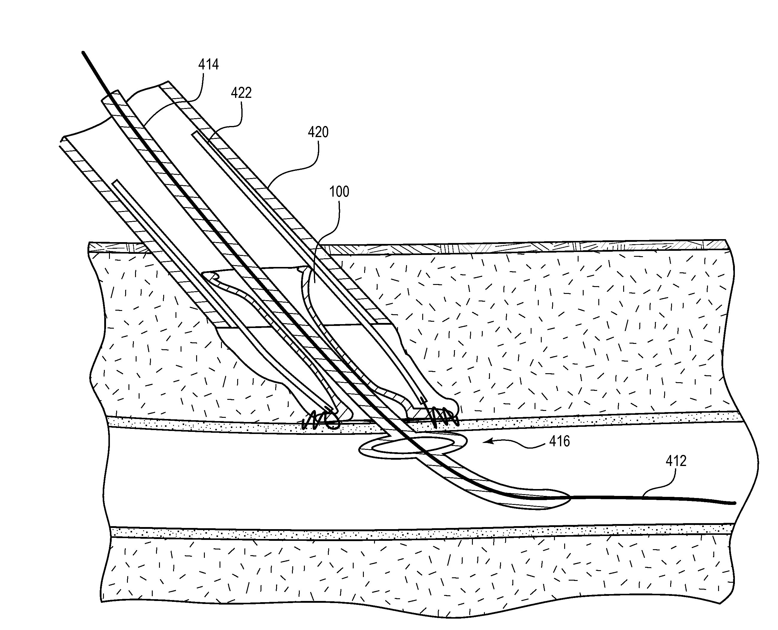
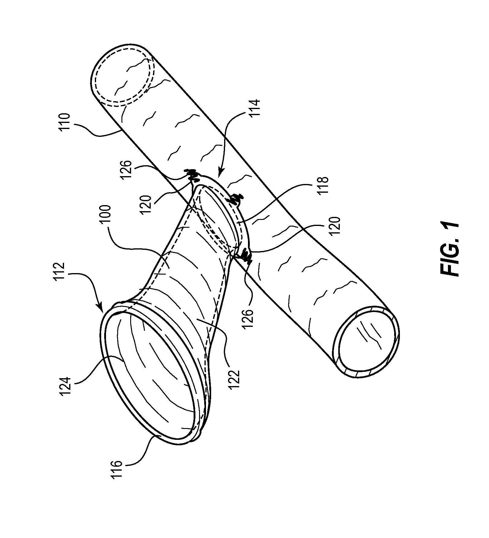
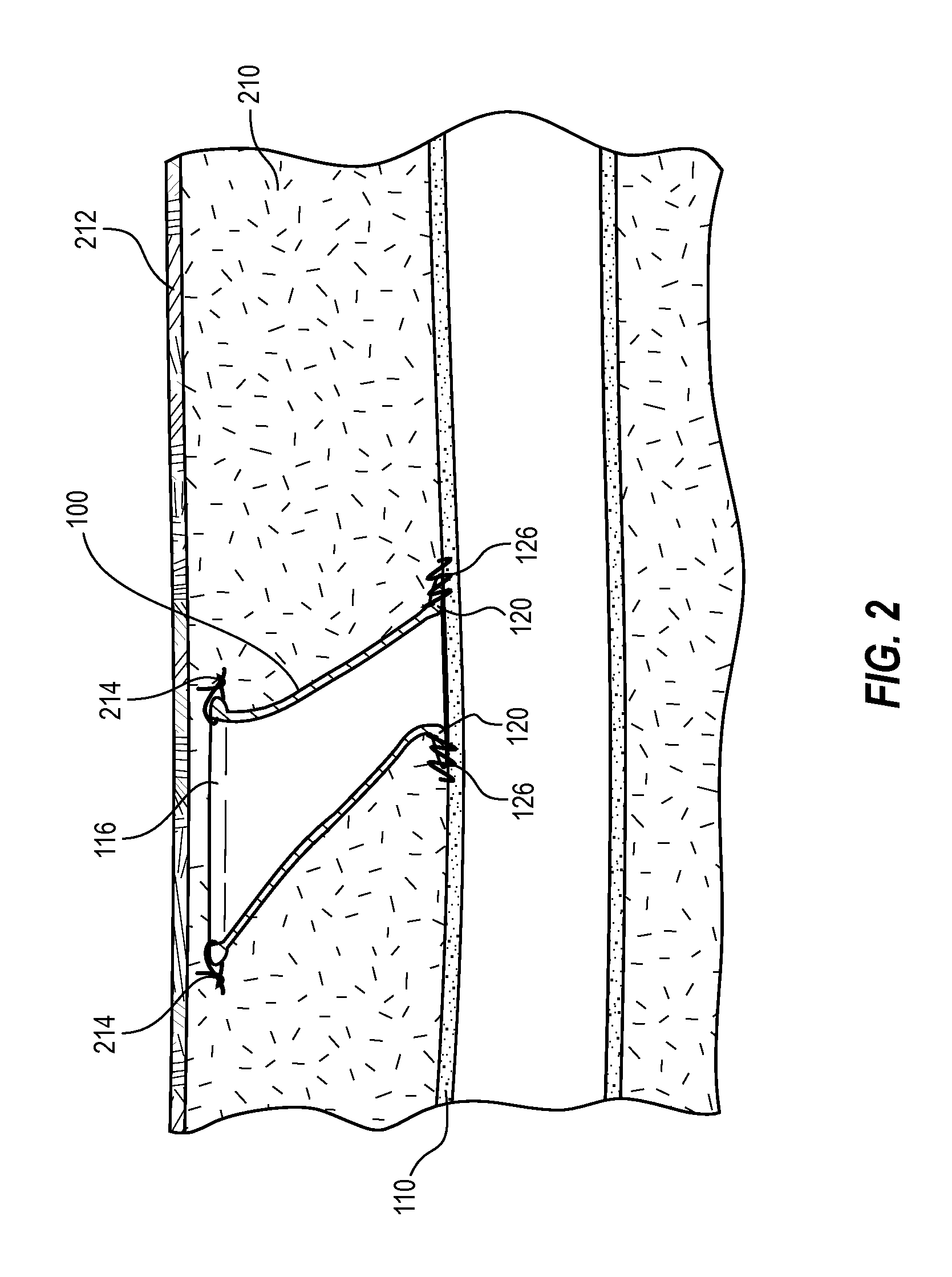
A subcutaneous needle conduit attaches directly to a blood vessel or other biological boundary structure. The subcutaneous needle conduit is tapered such that a proximal end is wider than a distal end. A body of the subcutaneous needle conduit guides the tip of a needle or other canula from the proximal end to the distal end. The subcutaneous needle conduit may be funnel-shaped. An elongated funnel shape may be used to selectively provide access to a plurality of desired access sites along an axis of a blood vessel. Other shapes, such as sluice-shaped, may also be used. The subcutaneous needle conduit may be located beneath the skin surface using, for example, tactile sensation, magnetism, metal detection, detection of a signal emitted from a minute transponder, detection of light emission, or through other detection methods.

Description

RELATED APPLICATION[0001]This application claims the benefit under 35 U.S.C. §119(e) of U.S. Provisional Application No. 61 / 171,512, filed Apr. 22, 2009, which is hereby incorporated by reference herein in its entirety.TECHNICAL FIELD[0002]This disclosure relates to subcutaneous vascular access ports.BACKGROUND INFORMATION[0003]Repetitive vascular access is used for treatments such as prolonged intravenous chemotherapy protocols and venous hemodialysis.[0004]Among the patients needing repeated vascular access are chemotherapy patients. A large number of chemotherapeutic agents are infused intravenously over multiple cycles during the treatment of a wide variety of neoplasms. Because many of these agents can cause pain and vessel thrombosis and sclerosis, these chemotherapeutic agents are generally infused into a larger central vein by means of a peripherally inserted central catheter or “PIC line” (e.g., a size 4 French (F) or lower diameter catheter may be inserted, usually, into a...

Claims


Application Information

Patent Timeline
IPC IPC(8): A61M5/32
CPCA61B17/064A61B17/068A61B17/11A61B2017/0647A61M39/0247A61B2017/1107A61M5/3287A61M39/0208A61B2017/0649
Inventor TEITELBAUM, GEORGE P.SHAOLIAN, SAMUEL M.POOL, SCOTT L.
Owner TEITELBAUM GEORGE P
Learn More