Data reorganization in non-uniform cache access caches

a data and cache access technology, applied in computing, memory adressing/allocation/relocation, instruments, etc., can solve the problems of large resistive-capacitive (rc) signal delay associated with long bus lines, increasing the number of processing elements on a chip, and increasing the number of processing elements on the chip. to achieve the effect of reducing access latency

Inactive Publication Date: 2010-10-28
IBM CORP
View PDF18 Cites 24 Cited by
  • Summary
  • Abstract
  • Description
  • Claims
  • Application Information

AI Technical Summary

Benefits of technology

[0008]Some embodiments comprise a method that includes setting direction bits for two separate cache lines. The first cache line may be located in one way of a bank of a NUCA cache, with the second cache line being located in another way of the cache. For the embodiments, the sets are horizontally distributed across the banks of the NUCA cache. In reorganizing data in the NUCA cache to reduce access latency, the embodiments move data of the first cache line to the second bank and data of the second cache line to the first bank. The embodiments move the data based upon a calculation which involves the direction bits for both cache lines.
[0011]Other embodiments comprise systems for reorganizing data in NUCA caches. The systems comprise a plurality of processors, a plurality of banks of a NUCA cache, and a cache controller. In the embodiments, the cache controller evaluates access latencies between the processors and banks storing cache lines requested by the processors. In performing the evaluations, the cache controller calculates access latencies for pairs of cache lines stored in pairs of banks to determine whether swapping the cache lines between the pairs of banks reduces access latency between one or both of the cache lines and one or more processors that last requested data of the cache lines.

Problems solved by technology

Increasing the number of processing elements on a chip starts to place severe demands on memory bandwidth because of the many execution contexts that could be all running simultaneously.
Therefore, the bandwidth to memory is starting to become a performance bottleneck.
In a very large cache memory comprising multiple banks, one problem that arises is the large resistive-capacitive (RC) signal delay associated with the long bus lines when driven at a high clock rate (e.g., 1 GHz).

Method used


Image

  • Data reorganization in non-uniform cache access caches
  • Data reorganization in non-uniform cache access caches
  • Data reorganization in non-uniform cache access caches

Examples


Embodiment Construction

[0020]The following is a detailed description of novel embodiments depicted in the accompanying drawings. The embodiments are in such detail as to clearly communicate the subject matter. However, the amount of detail offered is not intended to limit anticipated variations of the described embodiments. To the contrary, the claims and detailed description are to cover all modifications, equivalents, and alternatives falling within the spirit and scope of the present teachings as defined by the appended claims. The detailed descriptions below are designed to make such embodiments understandable to a person having ordinary skill in the art.

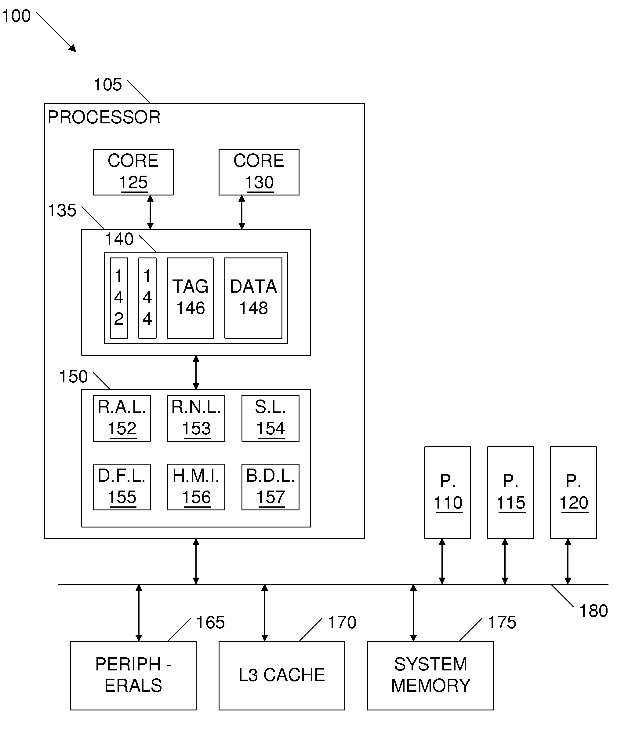
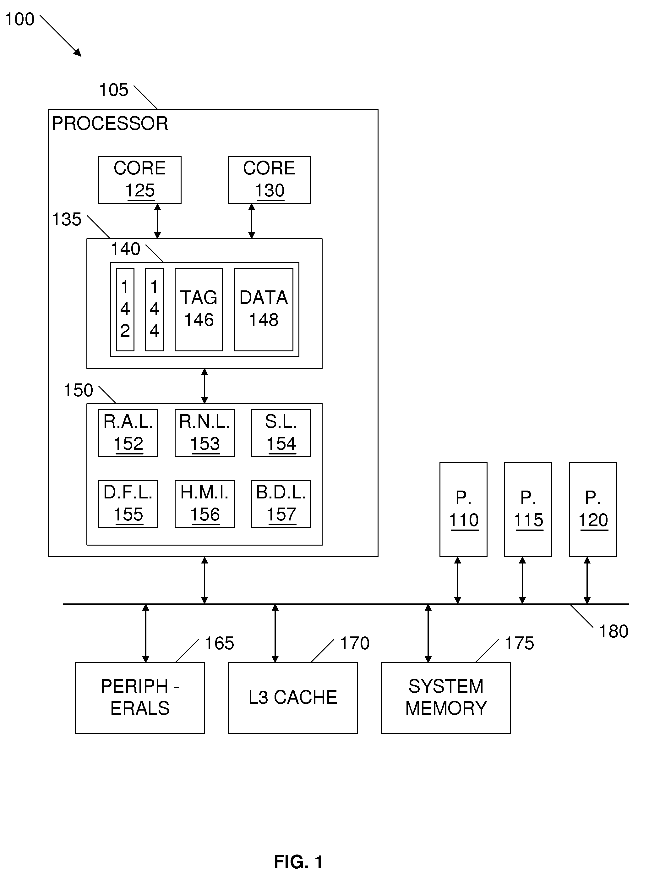
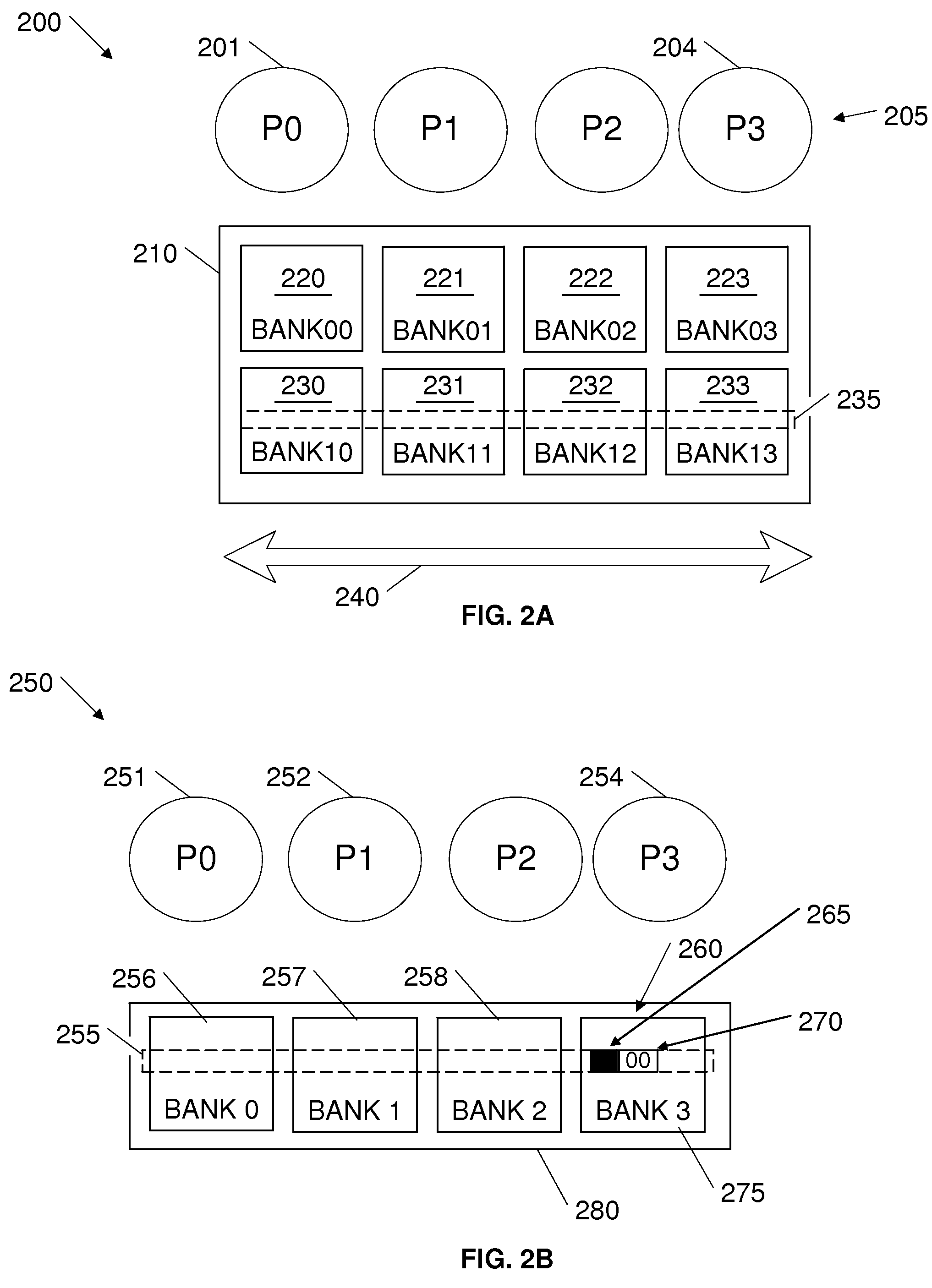
[0021]In various embodiments, a cache may have many blocks which individually store the various instructions and data values. The blocks in a cache may be divided into groups of blocks called sets or congruence classes. A set may refer to the collection of cache blocks in which a given memory block may reside. For a given memory block, there may be a ...


PUM


Abstract

Embodiments that dynamically reorganize data of cache lines in non-uniform cache access (NUCA) caches are contemplated. Various embodiments comprise a computing device, having one or more processors coupled with one or more NUCA cache elements. The NUCA cache elements may comprise one or more banks of cache memory, wherein ways of the cache are horizontally distributed across multiple banks. To improve access latency of the data by the processors, the computing devices may dynamically propagate cache lines into banks closer to the processors using the cache lines. To accomplish such dynamic reorganization, embodiments may maintain “direction” bits for cache lines. The direction bits may indicate to which processor the data should be moved. Further, embodiments may use the direction bits to make cache line movement decisions.

Description

TECHNICAL FIELD[0001]The present invention generally relates to the management of caches of a computing device. More specifically, the invention relates to reorganizing data in non-uniform cache access (NUCA) caches.BACKGROUND[0002]Cache memories have been used to improve processor performance, while maintaining reasonable system costs. A cache memory is a very fast buffer comprising an array of local storage cells used by one or more processors to hold frequently requested copies of data. A typical cache memory system comprises a hierarchy of memory structures, which usually includes a local (L1), on-chip cache that represents the first level in the hierarchy. A secondary (L2) cache is often associated with the processor for providing an intermediate level of cache memory between the processor and main memory. Main memory, also commonly referred to as system or bulk memory, lies at the bottom (i.e., slowest, largest) level of the memory hierarchy.[0003]In a conventional computer sy...

Claims


Application Information

Patent Timeline
Patent Type & Authority Applications(United States)
IPC IPC(8): G06F12/08G06F12/00
CPCG06F12/0846G06F12/0811
Inventor BALAKRISHNAN, GANESHBELL, GORDON B.KRISHNA, ANILRAMANI, SRINIVASAN
Owner IBM CORP
Why Eureka
Try Eureka