Inertial separator
a separator and inner tube technology, applied in the direction of single-direction vortex, chemical/physical processes, vortex flow apparatus, etc., can solve the problems of high operating temperature, high production cost,
- Summary
- Abstract
- Description
- Claims
- Application Information
AI Technical Summary
Benefits of technology
Problems solved by technology
Method used
Image
Examples
example 1
[0075]This example demonstrates the preparation of a composition according to an embodiment of the invention.
[0076]Injection mold grade cyclic olefin copolymer (Topas® 6015S04, Topas Advanced Polymers Inc., Florence, Ky.) is mixed with powdered polyhedral oligomeric silsesquioxane (TriSilanolIsobutyl POSS®, S01450, Hybrid Plastics, Inc., Hattiesburg, Miss.), impact modifier (KRATON® G1654H SEBS polymer, Kraton Polymers U.S., LLC, Houston, Tex.), and colorant (Green Pigmented Polypropylene 0M64620047 (that includes a hindered light stabilizer and an antioxidant), Clariant, Coventry, R.I.), in a co-rotating twin screw extruder to produce pellets for use in injection molding. The percentages by weight are as follows: cyclic olefin copolymer 81%, polyhedral oligomeric silsesquioxane 3%, impact modifier 11%, and colorant 5%.
example 2
[0077]This example demonstrates that a composition according to an embodiment of the invention is suitable for producing an inertial separator.
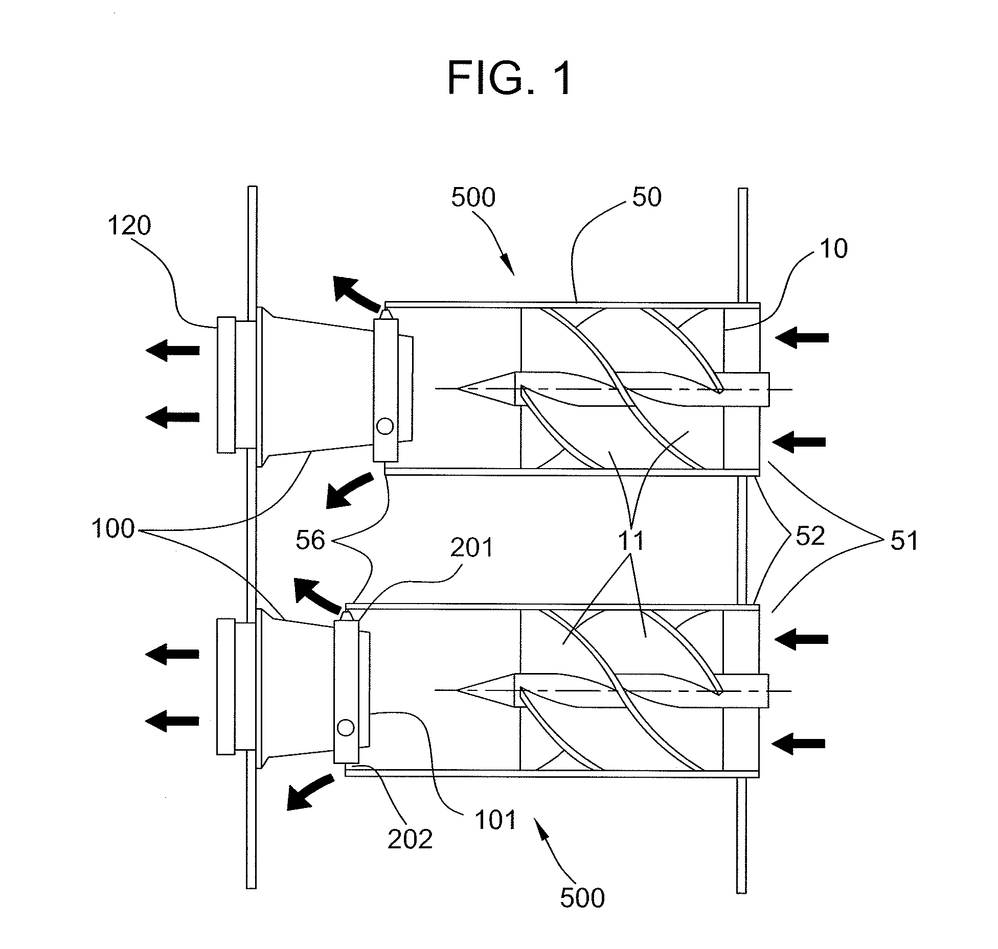
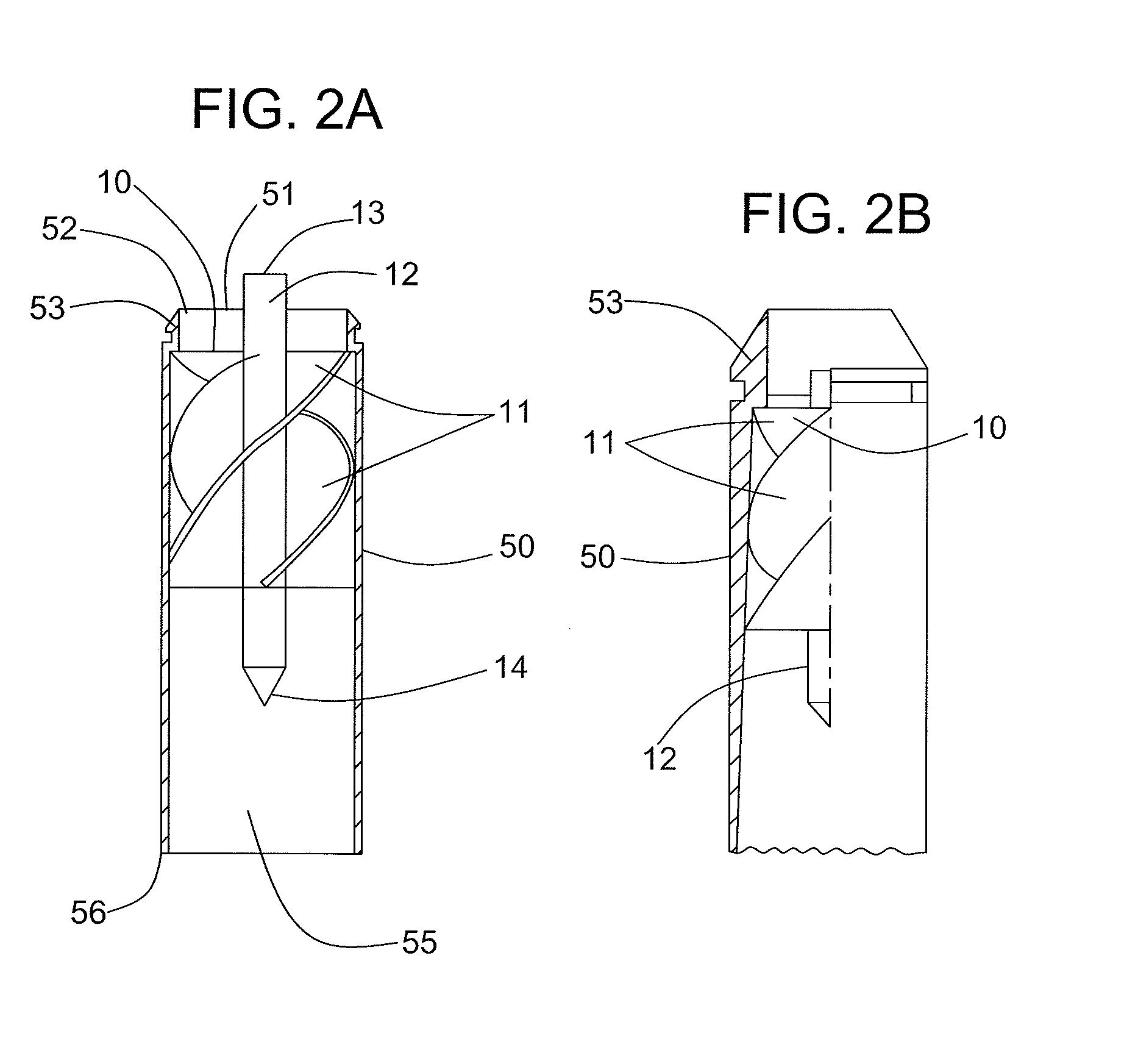
[0078]The composition according to Example 1 is injection molded to form inertial separators having the general format shown in FIGS. 1-3. The walls of the tubular housing have a thickness in the range of about 0.3 mm. The components of the separators are non-porous.
example 3
[0079]This example demonstrates the preparation of a composition according to another embodiment of the invention.
[0080]Injection mold grade cyclic olefin copolymer (Topas® 6015S04, Topas Advanced Polymers Inc., Florence, Ky.) is mixed with powdered polyhedral oligomeric silsesquioxane (TriSilanolIsobutyl POSS®, S01450, Hybrid Plastics, Inc., Hattiesburg, Miss.), impact modifier (KRATON® G1654H SEBS polymer, Kraton Polymers U.S., LLC, Houston, Tex.), flame retardant (Decabromodiphenyl Ethane Grade, Firemaster® 2100, Great Lakes Chemical Corporation, West Lafayette, Ind.), synergist (Antimony trioxide Red Star® Sb2O3, Great Lakes Chemical Corporation, West Lafayette, Ind.), mold release agent (isotactic polypropylene Hival® 2420, Ashland, Inc., Covington, Ky.), pigment (Carbon Black Vulcan 9A32, Cabot Corporation, Alpharetta, Ga.), hindered amine light stabilizer (Uvinul 5050H, BASF Corporation, Florham Park, N.J.), and antioxidant (Phenolic / Phosphite Blend Process Antioxidant, Irgan...
PUM
| Property | Measurement | Unit |
|---|---|---|
| Composition | aaaaa | aaaaa |
| Color | aaaaa | aaaaa |
Abstract
Description
Claims
Application Information
 - R&D
- Intellectual Property
- Life Sciences
- Materials
- Tech Scout
- Unparalleled Data Quality
- Higher Quality Content
- 60% Fewer Hallucinations
Browse by: Latest US Patents, China's latest patents, Technical Efficacy Thesaurus, Application Domain, Technology Topic, Popular Technical Reports.
© 2025 PatSnap. All rights reserved.Legal|Privacy policy|Modern Slavery Act Transparency Statement|Sitemap|About US| Contact US: help@patsnap.com


