
Wind turbines having control for network faults and operating method thereof

a technology of wind turbines and faults, applied in the direction of electric generator control, machines/engines, mechanical equipment, etc., can solve the problems of island network formation, large risk of discrepancies in the island network, overloading or damage to components, etc., and achieve the effect of improving operation reliability

Active Publication Date: 2010-11-04
SIEMENS GAMESA RENEWABLE ENERGY SERVICE GMBH
View PDF17 Cites 40 Cited by
  • Summary
  • Abstract
  • Description
  • Claims
  • Application Information

AI Technical Summary

Benefits of technology

[0007]The invention is based on the object of improving wind energy installations of the type mentioned initially such that they have a better response to short circuits and island formation in the network.

Problems solved by technology

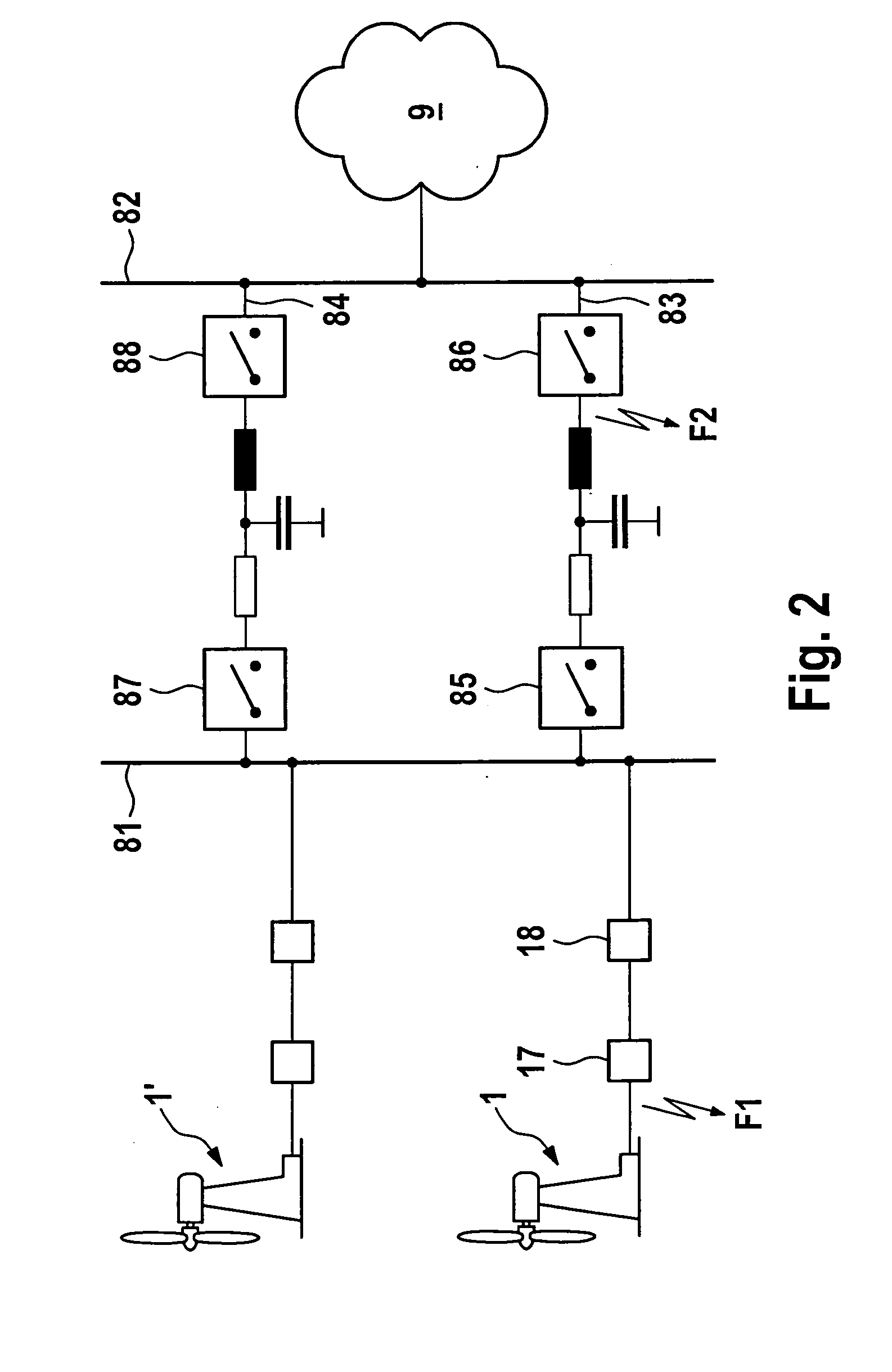
In electrical power transmission and distribution networks, it must always be expected that short circuits can result in island network formation.
In particular on reconnection after clearing of the network fault, this can lead to high equalizing currents flowing, which can result in overloading of or damage to components.
Furthermore, in the case of conventional power stations with synchronous generators, there is a risk of the discrepancies in the island network becoming so great that the generator will stall on connection to the rest of the network.
In many cases, this results in the wind energy installations having to be connected via relatively long spurs, with only little networking, of a power transmission network.
Because of this arrangement, wind energy installations are relatively easily affected by island formation in the network in the event of any disturbance.
Because of the greater discrepancy, equalization processes can occur to a more considerable extent on reconnection, thus resulting in the risk of damage.

Method used


Image

  • Wind turbines having control for network faults and operating method thereof
  • Wind turbines having control for network faults and operating method thereof
  • Wind turbines having control for network faults and operating method thereof

Examples


Embodiment Construction

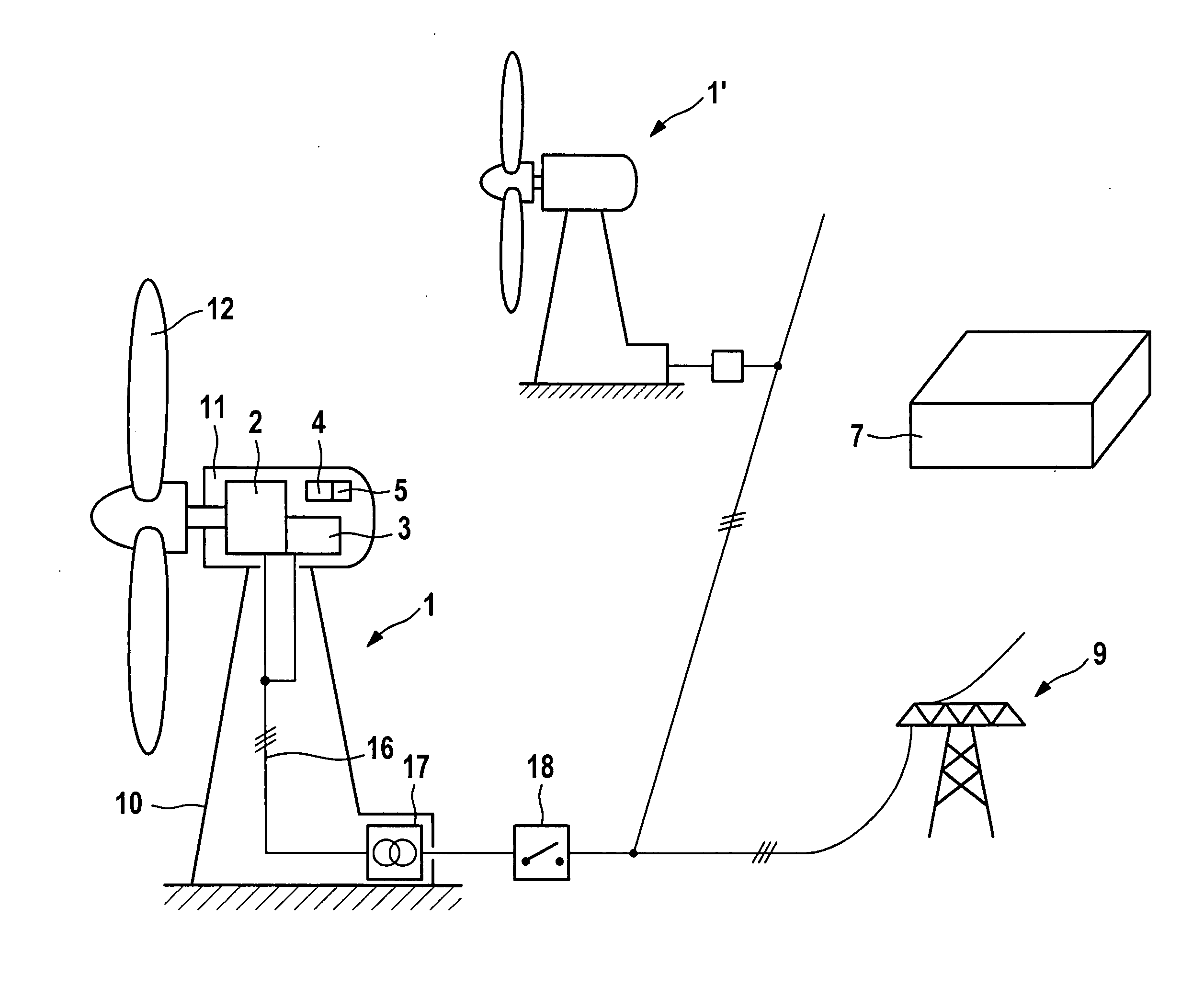
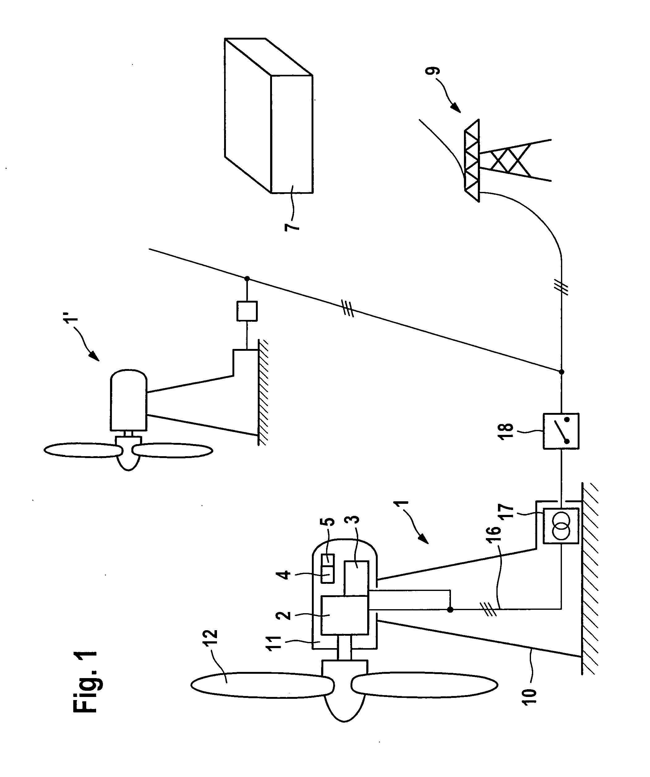
[0036]A wind energy installation according to a first exemplary embodiment of the invention comprises a tower 10 having a machine house 11 which is arranged at the upper end of the tower 10, such that it can pivot. A wind rotor 12 is arranged on the end face of the machine house 11 such that it can rotate, and drives a wind energy installation generator 2 via a rotor shaft (not illustrated). The generator 2 is connected to a converter 3. A control device 4 is also arranged in the machine house 11, and is connected via signal lines (not illustrated) to the generator 2 and to the converter 3, as well as to external signal sources (not illustrated).

[0037]The rotor 12 is driven by the wind and supplies mechanical energy via the rotor shaft to the generator 2, which correspondingly produces electrical power. The generator 2 is preferably a double-fed asynchronous machine with a stator winding and a rotor winding.

[0038]The stator winding is connected to a connecting line 16, which is conn...


PUM


Abstract

A network disturbance module for a control device of a wind energy installation having a generator driven by a wind rotor and a converter for producing electrical power fed into a network. The module includes a measurement device configured to measure at least one electrical parameter of the network, a detector configured to identify a network disturbance and output a switching signal, and a reference generator configured to produce a substitute reference vector for the converter based on the at least one electrical parameter. The module also includes a fault management unit comprising a fault classifier, the unit being configured to interact with the measurement device, detector, and reference generator such that, in the event of an undervoltage during island operation, a quick-action frequency regulator is activated. The regulator acts on the converter to vary a real-power feed P in the event of a discrepancy in a network frequency.

Description

REFERENCE TO RELATED APPLICATIONS[0001]This application is a national stage application under 35 USC 371 of International Application No. PCT / EP2008 / 008545, filed Oct. 9, 2008, which claims the priority of German Patent Application No. 10 2007 049 251.2, filed Oct. 12, 2007, the contents of which prior applications are incorporated herein by reference.FIELD OF THE INVENTION[0002]The invention relates to a wind energy installation having a generator, which is driven by a wind rotor, and having a converter for producing electrical power, which is fed into a network, and having a control device.BACKGROUND OF THE INVENTION[0003]In electrical power transmission and distribution networks, it must always be expected that short circuits can result in island network formation. In an island network, the voltage, frequency and the phase are no longer synchronized to the corresponding parameters in the main network. In particular on reconnection after clearing of the network fault, this can lea...

Claims


Application Information

Patent Timeline
Patent Type & Authority Applications(United States)
IPC IPC(8): H02P9/04
CPCF03D9/003F05B2270/337H02J3/386Y02E10/763Y02E10/72F03D9/255F03D9/257H02J2300/28H02J3/381Y02E10/76H02J3/40
Inventor FORTMANN, JENS
Owner SIEMENS GAMESA RENEWABLE ENERGY SERVICE GMBH
Learn More