Light Emitting Device

a technology of light-emitting devices and light-emitting tubes, which is applied in the direction of discharge tube luminescent screens, discharge tube/lamp details, luminescent compositions, etc., can solve the problems of poor color rendering performance, difficulty in blending colors, and uneven distribution of radiant flux intensity in the visible light region, so as to achieve high power efficiency, reduce the effect of size and color rendering performan

Active Publication Date: 2010-11-04
NICHIA CORP
View PDF8 Cites 21 Cited by
  • Summary
  • Abstract
  • Description
  • Claims
  • Application Information

AI Technical Summary

Benefits of technology

[0015]It is preferable that the light emitting device has a general color rendering index in a range from 75 to 99, which enables a light emitting device with higher color rendering performance.
[0016]It is preferable that the exciting light source is a light emitting element, and that the wavelength converting member comprises one fluorescent material or two or more kinds of fluorescent material having different compositions. Such a constitution enables a light emitting device of smaller size and high power efficiency.
[0017]It is preferable that the emission spectrum is characterized by a proportion of the energy intensity at the first wavelength to the energy intensity at a fifth wavelength being (Energy intensity at first wavelength) (Energy intensity at fifth wavelength)=100:25 to 100:200, where the fifth wavelength is 680 nm. This constitution further increases the intensity of emission in the red region thereby to provide a continuous emission spectrum like that of light from the sun or an incandescent lamp. The proportion of the energy intensity at the first wavelength to the energy intensity at the fifth wavelength is more preferably (Energy intensity at first wavelength):(Energy intensity at the fifth wavelength)=100:30 to 100:100, which enables an increase of the special color rendering index (R9) and an increase in the intensity of emission in the red region.
[0018]The wavelength converting member preferably comprises a nitride fluorescent material that includes at least one kind of group II el...

Problems solved by technology

However, the first light emitting device combines blue light and yellow light, and therefore has lower radiant flux in the blue-green region and in the red region than that of an incandescent lamp, thus resulting in uneven distribution of radiant flux intensity in the visible light region.
The second light emitting device has difficulty in blending colors and poor color rendering performance.
Since light emitted by an LED is sharp unlike the light emitted by a fluorescent lamp, ...

Method used


Image

  • Light Emitting Device
  • Light Emitting Device
  • Light Emitting Device

Examples


examples 1 to 8

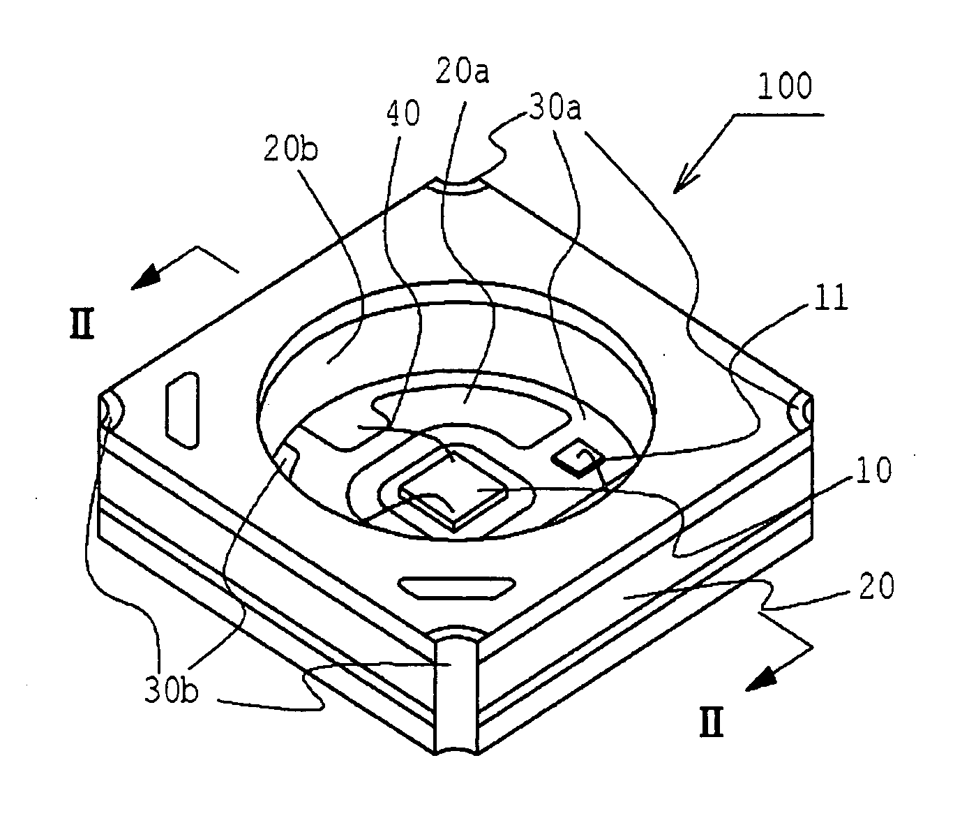
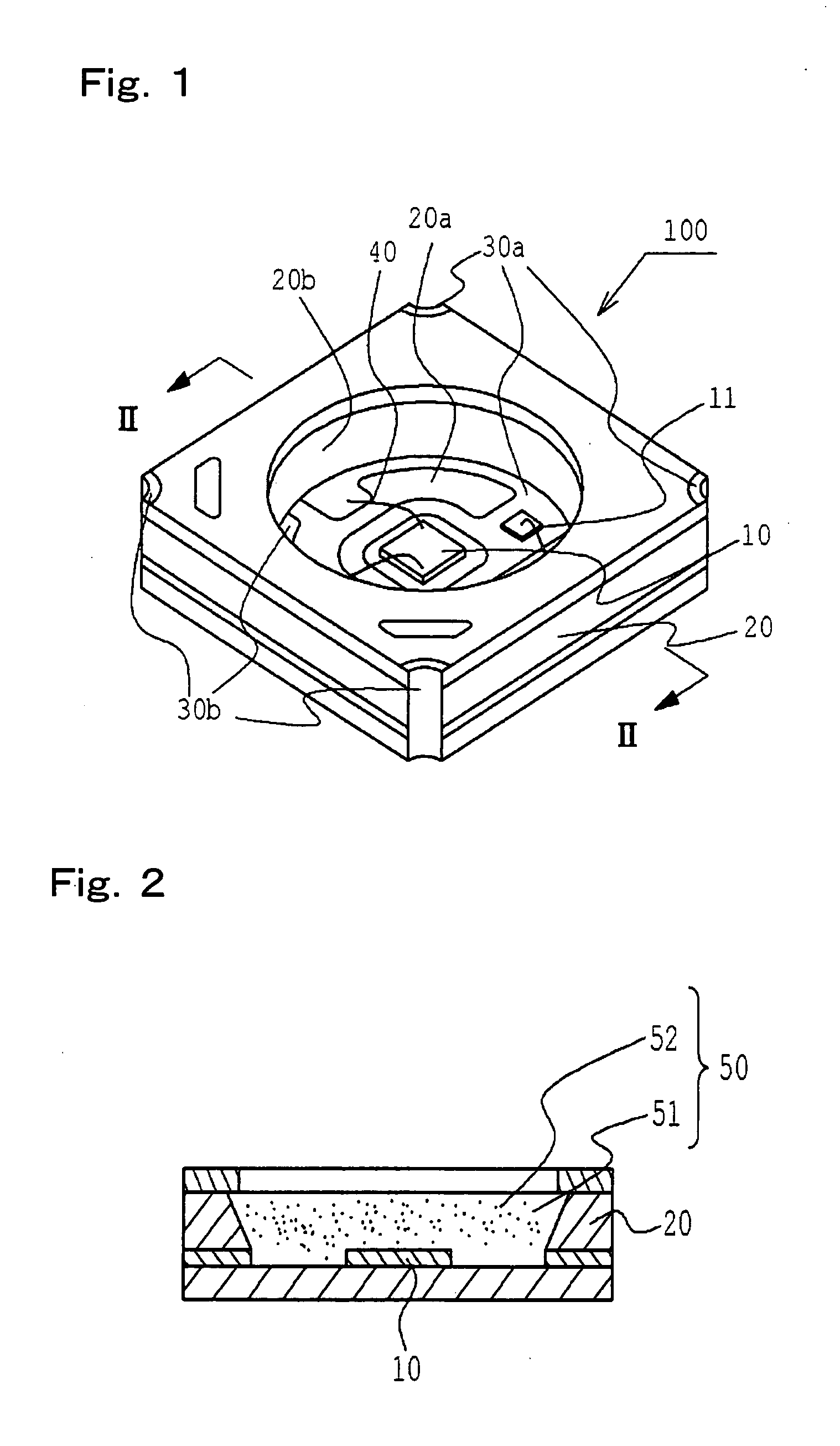
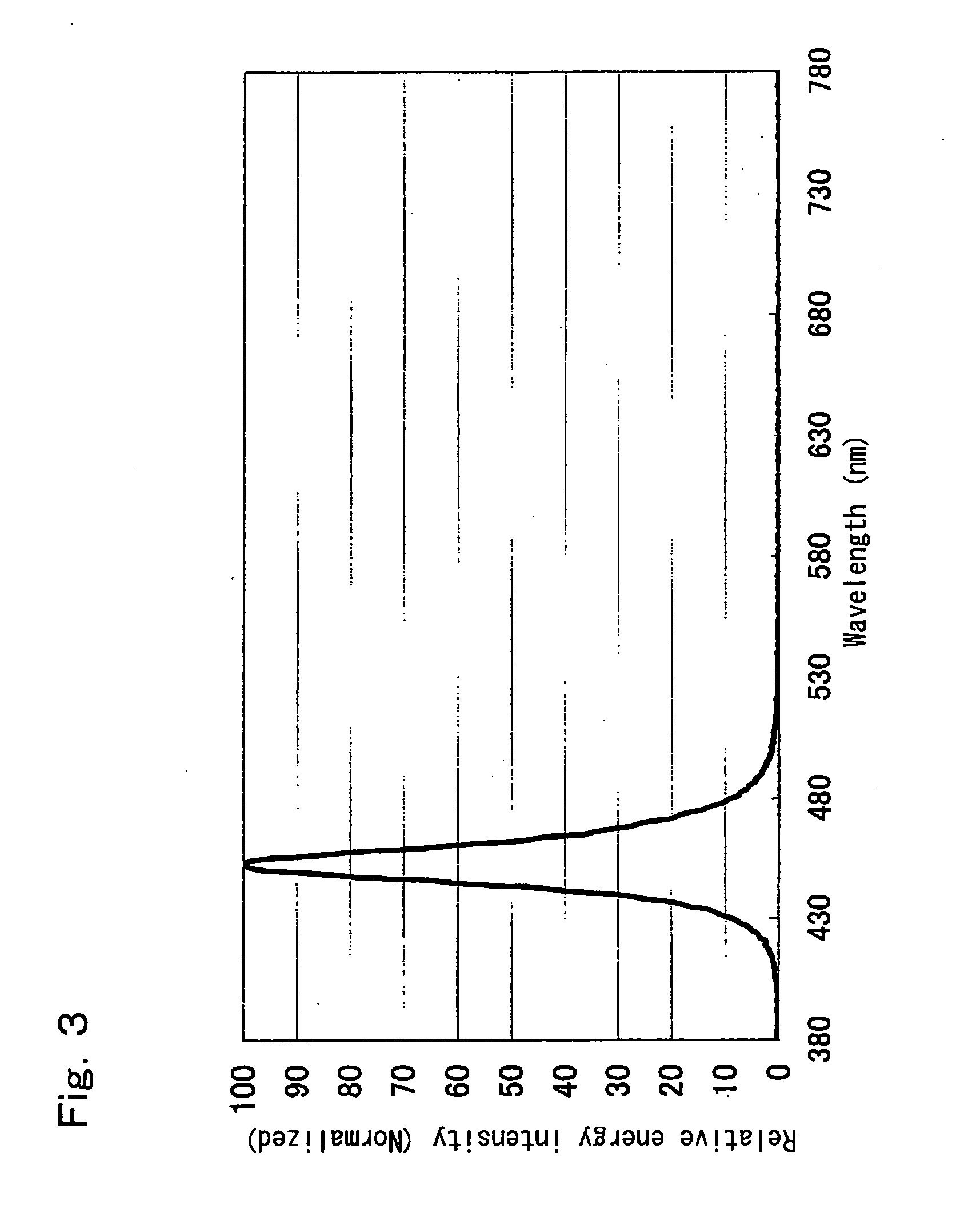
[0081]The light emitting device of the embodiment is used for the light emitting device of Examples 1 to 8. FIG. 1 is a schematic perspective view showing a light emitting device according to the embodiment. FIG. 2 is a sectional view showing the light emitting device according to the embodiment taken along lines II-II. FIG. 3 shows the emission spectrum of the light emitting element used in Example. FIG. 4 shows the emission spectrum of a fluorescent material having composition of Y3(Al, Ga)5O12:Ce. FIG. 5 shows the emission spectrum of a fluorescent material having composition of CaSiAlBXN3+X:Eu. The fluorescent material is excited with light having wavelength of 460 nm. FIG. 6 shows the emission spectra of Examples 1 to 8. Description of the light emitting device 100 of Examples will be partially omitted in consideration of the description of the light emitting device of the embodiment. Light colors and chromatic coordinates referred to in this specification are based on the CIE ...

examples 9 to 17

[0089]In Examples 9 to 17, an alkaline earth metal element aluminate fluorescent material having a composition of Sr4Al14O25:Eu was used in addition to the fluorescent material 52 of Examples 1 to 8. FIG. 7 shows the emission spectrum of a fluorescent material having composition of Sr4Al14O25:Eu. FIG. 8 shows the emission spectrum of Examples 9 to 17.

[0090]The light emitting devices of Examples 9 to 17 are the same as the light emitting devices 100 of Examples 1 to 8 except for the fluorescent material 52. In Examples 9 to 17, a YAG fluorescent material having composition of Y3(Al, Ga)5O12:Ce, a nitride fluorescent material having composition of CaSiAlBXN3+X:Eu (x>0), and an alkaline earth metal element aluminate fluorescent material of Sr4Al14O25:Eu were used for the fluorescent material 52. The alkaline earth metal element aluminate fluorescent material of Sr4Al14O25:Eu emits light with a somewhat broad emission spectrum having a peak emission wavelength around 495 nm, when excite...


PUM


Abstract

A light emitting device having a wavelength converting member for absorbing light from a pumping light source and converting its wavelength. Assuming a wavelength where the light from the pumping light source has a maximum energy intensity is a first wavelength, a wavelength where the light from the wavelength converting member has a maximum energy intensity is a second wavelength, a wavelength between the first and second wavelengths where emission spectrum of the light emitting device has a minimum energy intensity is a third wavelength, and a wavelength of 650 nm is a fourth wavelength, the ratio of energy intensity between the first and third wavelengths is 100:15-150, and the ratio of energy intensity between the first and fourth wavelengths is 100:45-200.

Description

TECHNICAL FIELD[0001]The present invention relates to a light emitting device used in a liquid crystal backlight light source, lighting apparatus, backlight light source for display, flash of a camera, auxiliary light source for movies, etc., and particularly to a light emitting device requiring color rendering performance.BACKGROUND ART[0002]The fluorescent lamp is used as a popular lighting apparatus. However, growing concern for environmental pollution increases the demand for light sources which are free of mercury, and light emitting devices based on light emitting elements such as light emitting diodes (hereinafter referred to as LEDs) or laser diodes (hereinafter referred to as LDs) are attracting much attention.[0003]Light emitting devices based on the light emitting elements are small in size, high in power efficiency and are capable of emitting light of vivid colors. Furthermore, such light emitting elements are semiconductor devices free of failure such as burnout. These ...

Claims


Application Information

Patent Timeline
IPC IPC(8): H01J1/62H01L33/50
CPCC09K11/662C09K11/7771C09K11/7774C09K11/7785H01L33/50H01L2224/48247H01L33/504H01L2224/48091H01L2924/00014
Inventor TAKASHIMA, SUGURUAIHARA, MASATOTAKEICHI, JUNJINAITOU, TAKAHIROTAMAKI, HIROTOKISHIMOTO, TOMOHISA
Owner NICHIA CORP
Why Eureka
Try Eureka