
Information equipment apparatus

a technology of information equipment and apparatus, applied in the direction of unauthorized memory use protection, digital output to print units, instruments, etc., can solve the problems of not being able to allow a plurality of users to use the apparatus simultaneously, not being able to directly identify the person operating other switches or touch panels, and not being able to solve the problem of security aspects

Active Publication Date: 2010-11-04
KONICA MINOLTA BUSINESS TECH INC
View PDF15 Cites 30 Cited by
  • Summary
  • Abstract
  • Description
  • Claims
  • Application Information

AI Technical Summary

Benefits of technology

[0019]The present invention was made for solving the above problems, and an object of the present invention is to provide an information equipment apparatus that, without having to carry out a special operation and change the authentication state of operators between operations, can carry out control operations according to the operator of the received operation.
[0020]Further, another object of the present invention is to provide an information equipment apparatus wherein it is possible to simplify the configuration of the interface with the operator for identifying the operator and to prevent erroneous recognition of operations.

Problems solved by technology

As has been described above, since the conventional individual person identification by card authentication or biometric information authentication recognizes the operations made after authentication as those made by that authenticated user, the number of persons that can be managed at the same time is only one person, and it was cumbersome because it was not possible to switch users unless the authentication state of one user has been released.
In the technology of Patent Document 1 of adding fingerprint verification mechanism to the switches of specific functions, it is not possible to directly identify the person operating other switches or touch panel.
Because of this, it is inevitable that the operations of these operation members are handled as having been made by the user authenticated at the time of operating specific function switches, and eventually, only one authenticated user can be managed at the same time by the apparatus, and it is not possible to allow a plurality of users to use the apparatus simultaneously.
Further, if the operations of other operation members are handled as the operations by the user who was authenticated at the time of operation of switches of specific functions, it is likely that the operations made by another person of those operation members are handled as the operations made by the authenticated person, there was also a problem in security aspects.
Because of this, in units of an operation section, an operation of releasing the authentication or a switching operation, etc., is necessary for switching between users, and not only the switching of users is cumbersome, but also, it is likely that the operations made by another person in the authenticated state are handled as the operations made by the authenticated person, there was also a problem in security aspects.
As has been explained above, in the conventional individual person authentication by image forming apparatus, etc., since the operations received from an operation section in the authenticated state are recognized as the operations made by the authenticated user himself or herself, it is not possible to recognize distinctly the operations by an authenticated user and other operations.
For example, even unintentional operations (erroneous operations) caused by some object falling on the operation section or by the edge part of a document touching the operation section, etc., or the operations made by some other person while the authenticated user has temporarily gone away from the apparatus (identity theft operations) are likely to be recognized wrongly as having been made by the authenticated user.
In the technology of Patent Document 1 of adding fingerprint verification mechanism to the switches of specific functions, although it is possible to consider preventing erroneous recognitions such as the above by incorporating fingerprint authentication mechanisms in all the operation members, if the number of operation members becomes large, there are the problems that the mounting layout becomes difficult, and the cost becomes high.
The same is also true even in the case of the technology of Patent Document 3 wherein individual person authentication by fingerprint authentication, etc., has been combined with data communication utilizing human body communication, and for example, even if erroneous recognitions such as the above are prevented by incorporating fingerprint authentication sensor, etc., in all operation members of all operation sections in which a plurality of operation members have been provided, again there are the problems that the mounting layout of operation members and fingerprint authentication sensors becomes difficult, and the cost becomes high.
In these Patent Documents 1 and 3, if an attempt is made to prevent erroneous recognition of operation, in either case, there is the problem that the configuration of the interface with the operator that becomes necessary for identifying the operator becomes complex.

Method used


Image

  • Information equipment apparatus
  • Information equipment apparatus
  • Information equipment apparatus

Examples


example 1

[0150 of Multiple Operation Sections Configuration:

[0151]FIG. 8 shows an example of the configuration in which multiple operation panels, with an electrode sheet having the function of an antenna in human body communication provided on the surface, are provided in a multifunction peripheral.

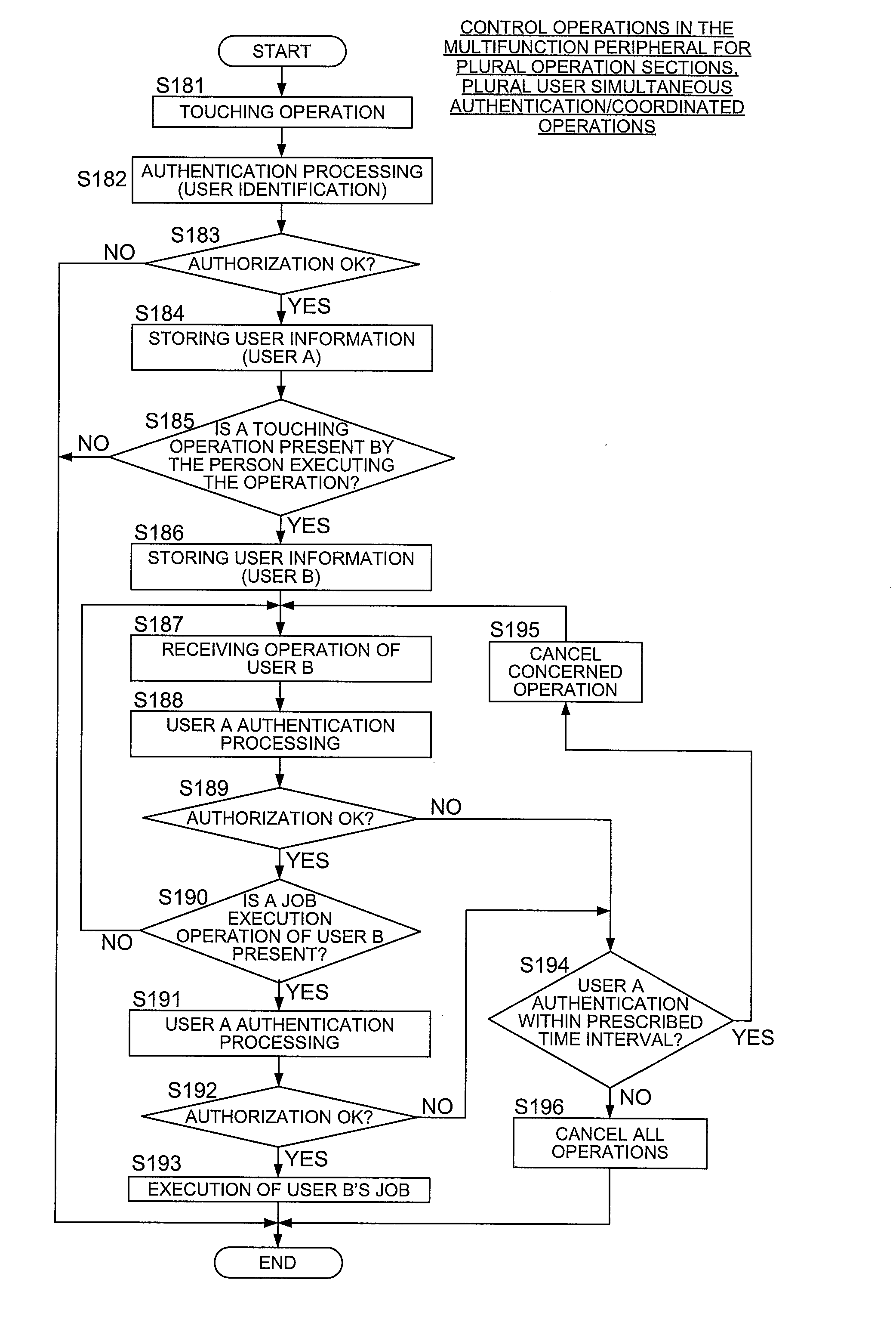
[0152]In a multifunction peripheral 10, etc., in which user authentication is carried out using human body communication when an operation is made on the operation panel as described above, since user identification can be made for each operation, for example, regarding various operations that are received at the same instant of time from a plurality of operation panels, to identify the individual users by carrying out different user authentications, and when it is possible to execute in parallel the different control operations (processing) for the different control operations (when they do not conflict with each other), it also becomes possible to execute those different control operations in p...

example 2

[0160 of Multiple Operation Sections Configuration:

[0161]FIG. 10 shows an example of the configuration when a plurality of large sized operation panels (externally connected operation sections) explained in FIG. 8 are provided in a multifunction peripheral.

[0162]The multifunction peripheral 70 of the present example has a configuration in which two operation panels configured as externally attached operation panels and which have the same configuration as the first operation panel 62 described above, and in detailed terms, a first operation panel 72 (the first operation section) and a second operation panel 74 (the second operation section), and no operation panel is provided on the top part of the front surface of the apparatus body 70a. Further, the multifunction peripheral 70, similar to the multifunction peripheral 60 described above, is provided with the function of accepting simultaneous operations in these two operation panels, the function of carrying out individual authenti...

example 3

[0165 of Multiple Operation Sections Configuration:

[0166]FIG. 11 shows an example of the configuration when the large sized operation panel explained in FIG. 8 is connected wirelessly to a multifunction peripheral.

[0167]The multifunction peripheral 80 of the present example is provided with a large sized first operation panel 82 (first operation section / wireless operation section) that is separated from the apparatus body 80a and that is connected wirelessly to the apparatus body 80a, and a second operation panel 84 (the second operation section / main unit operation section) that is provided at the top part of the front panel of the apparatus body 80a. Further, the multifunction peripheral 80, similar to the multifunction peripherals 60 and 70 described above, is provided with the function of accepting simultaneous operations in these two operation panels, the function of carrying out individual authentications for the simultaneous operations, and the function of carrying out simulta...


PUM


Abstract

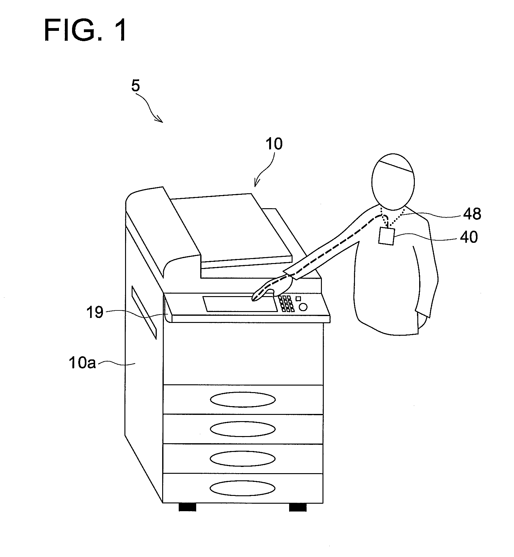
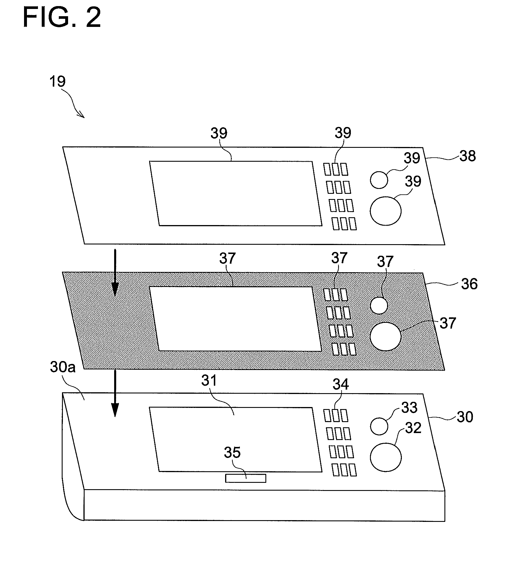
An information equipment apparatus provided with: an operation section; a communication section which carries out communication with a terminal apparatus storing identification data of an operator related to an operation in the operation section, by using a human body of the operator as a communication path; and a control section which, in coordination with a detection of the operation in the operation section, executes an identification of the operator based on the identification data by carrying out communication with the terminal apparatus via the communication section, and according to a result of the identification, controls a control operation corresponding to the operation in the operation section.

Description

CROSS REFERENCE TO RELATED APPLICATION[0001]This application is based on Japanese Patent Application No. 2009-112325 and No. 2009-112338 respectively filed on May 1, 2009 and May 1, 2009 with Japanese Patent Office, the entire content of which is hereby incorporated by reference.BACKGROUND OF THE INVENTION[0002]1. Technical Field[0003]The present invention relates to information equipment apparatus that identifies operators using human body communication.[0004]2. Prior Art[0005]The number of persons that can be authenticated at one time is only one person in the general purpose individual person authentication (user authentication) in image forming apparatuses, etc., for example, in password authentication or card authentication, or biometric information authentication such as fingerprint, veins, etc. Normally, the control operations are made so that the single operation section provided in the apparatus body is released to the authenticated user and various types of operations are ...

Claims


Application Information

Patent Timeline
IPC IPC(8): G06F15/00G06F21/00
CPCG06F21/34H04N1/00326H04N1/00408H04N2201/0094H04N1/00496H04N1/00514H04N1/00411
Inventor AOYAMA, MOTOAKIKUMAKURA, SHUNICHIWATANABE, YUKIO
Owner KONICA MINOLTA BUSINESS TECH INC
Learn More